Copyright © 2026 Akamai Technologies Canada Inc.
Permission is granted to copy, distribute and/or modify this document under the terms of the GNU Free Documentation License, Version 1.2 or any later version published by the Free Software Foundation; with no Invariant Sections, no Front-Cover Texts, and no Back-Cover Texts. A copy of the license is included in the section entitled "GNU Free Documentation License".
The fonts used in this guide are licensed under the SIL Open Font License, Version 1.1. This license is available with a FAQ at: http://scripts.sil.org/OFL
Copyright © Raph Levien, http://levien.com/, with Reserved Font Name: "Inconsolata".
1. About this Guide
This guide covers PacketFence installation and day-to-day administration. It provides comprehensive instructions for system requirements assessment, initial deployment, network integration, authentication configuration, and ongoing maintenance. The guide covers both standalone and distributed deployments, including certificate management, database configuration, and integration with external authentication systems like Active Directory and LDAP.
Find the latest version at https://www.packetfence.com/docs/
1.1. Other Guides
- Clustering Guide
-
Comprehensive guide for setting up active/active clustering environments with HAProxy load balancing, Keepalived for high availability, and Galera database clustering. Includes advanced configuration for layer-3 clusters and troubleshooting cluster synchronization issues.
- Developer’s Guide
-
Technical documentation for customizing PacketFence including REST API usage, captive portal theming and functionality modifications, SNMP module development, supporting new network equipment, and application code customizations. Essential for integrators and developers extending PacketFence.
- Network Devices Configuration Guide
-
Device-specific configuration instructions for over 80 supported network vendors including switches (802.1X, MAC authentication, VLAN assignment), wireless controllers and access points. Covers RADIUS, SNMP configuration and integration with various network equipment manufacturers.
- Upgrade Guide
-
Step-by-step upgrade procedures with version-specific compatibility changes, manual configuration migration steps, database schema updates, and critical upgrade notes. Includes troubleshooting for common upgrade issues and rollback procedures.
1.2. Other sources of information
- https://www.packetfence.com/news
-
Release announcements with detailed feature descriptions, performance improvements, security updates, and comprehensive bug fix listings organized by PacketFence version.
- PacketFence Users Mailing List
-
Community support forum for installation help, configuration questions, troubleshooting assistance, and best practices discussions. Active community of users and developers providing peer-to-peer support.
- PacketFence Announcements
-
Public announcements including new releases, security warnings and important updates regarding PacketFence. Low-traffic list for staying informed about major PacketFence developments.
- PacketFence Development
-
Discussion of PacketFence development including feature requests, architectural discussions, patch submissions and development coordination. For developers contributing to PacketFence core.
Package and release tarballs include the PacketFence guide files.
2. Introduction
PacketFence is a fully supported, trusted, Free and Open Source network access control (NAC) system. It features a captive portal for registration and remediation, centralized wired and wireless management, 802.1X support, layer-2 isolation of problematic devices, and integration with IDS, vulnerability scanners and firewalls. PacketFence effectively secures networks from small to very large heterogeneous environments. Visit https://www.packetfence.com for more details.
3. System Requirements
3.1. Assumptions
PacketFence reuses many components in an infrastructure. Nonetheless, it will install the following ones and manage them itself:
- database server (MariaDB)
- web server (Apache)
- DHCP server (PacketFence)
- RADIUS server (FreeRADIUS)
- firewall (iptables)
This guide assumes all components run on the same server as PacketFence.
Understanding these components and GNU/Linux is required. PacketFence installs and manages these services. Ensure other services start automatically with your operating system.
3.2. Minimum Hardware Requirements
Minimum server hardware recommendations
- Intel or AMD CPU 3 GHz, 4 CPU cores
- 16 GB of RAM
- 200 GB of disk space (RAID-1 recommended)
- 1 network card (2 recommended)
3.3. Operating System Requirements
PacketFence supports the following operating systems on the x86_64 architecture:
- Red Hat Enterprise Linux 8.x Server
- Debian 12.x (Bookworm)
Ensure you can install additional packages from your distribution. Red Hat Enterprise Linux requires Red Hat Network subscription.
Other distributions like RHEL or Debian derivatives may work but are not officially supported or documented.
Other Recommendations
- Use logical volume management (LVM) to allocate space
4. Installation
Install PacketFence using the Zero Effort NAC (ZEN) appliance or standard package repository on GNU/Linux installations.
4.1. Installing PacketFence from the ZEN
ZEN (Zero Effort NAC) edition enables rapid PacketFence deployment. It’s a fully installed, preconfigured virtual appliance compatible with VMware ESX/ESXi, Microsoft Hyper-V and other products. This section covers VMware-based deployment. Xen-based hypervisors are not supported.
Download the ZEN here: https://www.packetfence.com/download/#zen
4.1.1. Virtual Machine
Tested with VMware ESXi, Fusion and Workstation with 16 GB RAM dedicated to the VM. Compatible with other VMware products. Requires 64-bit CPU host for long mode support. PacketFence ZEN comes as a pre-built OVF virtual disk. Import the OVF using vSphere Client or vCenter for ESX hypervisors.
The VM’s first network card receives IP through DHCP.
The virtual appliance passwords are:
- Login: root
- Password: p@ck3tf3nc3
4.1.2. Import to ESX
Make sure that there is only one virtual network card created, and also make sure that the vEthernet is connected to a virtual switch (vSwitch). That virtual network card will be used as the PacketFence management interface.
4.1.3. Import to VMware Player/Workstation for Linux
Newer versions of VMware Player handle VLAN trunking a lot better. With that in mind, we can use a single interface on the VM. So, ensure that the VM host is plugged into a physical trunk port with VLAN 1,2,3,5,10 and 200 as the allowed VLAN. These VLANs will be used later in configuration examples.
4.2. Installing PacketFence from the ISO
The ISO edition of PacketFence allows you to install PacketFence on Debian 12 with minimal effort. Instead of manually installing Debian 12 and installing PacketFence after, this will perform both tasks and select the optimal parameters and best practices for installing the operating system.
Download the ISO here: https://www.packetfence.com/download/#packages
4.2.1. Machine specifications
This setup has been tested using VMware ESXi, Proxmox VE and VirtualBox and works with any hypervisor PacketFence supports as well as bare-metal servers.
A virtual machine or server with 16 GB of RAM dedicated to machine as well as 4 CPUs is required. Allocate at least 200GB of disk space for PacketFence.
4.2.2. Installing the ISO to a virtual machine
Provision a virtual machine with the specifications above, mount the ISO in the CD/DVD drive of the machine and start it. The installer will open. Follow the instructions on screen to complete the installation.
4.2.3. Installing the ISO to a bare-metal server
First, ensure the server follows the specifications above, then burn the ISO onto a DVD or USB key and boot it on the server. The installer will open. Follow the instructions on screen to complete the installation.
4.3. Installing PacketFence on existing Linux
PacketFence provides repositories for RHEL 8 and Debian 12 (bookworm) with all required dependencies.
Repository Benefits:
- Streamlined installation with dependency management
- Pre-built RPM (EL8) and DEB (Debian 12) packages
- Simplified upgrade process
4.3.1. Common Prerequisites
All Systems:
- Minimal OS installation (no additional packages)
- UEFI Secure Boot disabled (if applicable)
- System updated to latest patches
- No SELinux or Apparmor enabled
- No firewalld (Iptables is used)
4.3.2. RHEL 8 System Preparation
Security Configuration
# Disable firewall and SELinux (required)systemctl disable --now firewalldsed -i 's/^SELINUX=.*/SELINUX=disabled/' /etc/selinux/config# Update systemyum update# Reboot to apply SELinux changesreboot
PacketFence will not work properly if SELinux is enabled. Explicitly disable
SELinux in the /etc/selinux/config file and reboot the machine.
Kernel and Development Tools
Prerequisites:
- Valid RHEL subscription for dependency installation
- Latest kernel running
# Install kernel development package for current kernelyum install kernel-devel-$(uname -r)# Remove conflicting container tools (PacketFence uses docker)yum remove runc podman# Import PacketFence GPG key (required for EL8)rpm --import https://inverse.ca/downloads/GPG_PUBLIC_KEY
PacketFence Software Installation
# Install PacketFence repositoryyum localinstallhttps://www.packetfence.org/downloads/PacketFence/RHEL8/packetfence-release-15.1.el8.noarch.rpm# Install PacketFence with all dependencies# Includes: MariaDB, FreeRADIUS, DHCP serveryum install --enablerepo=packetfence packetfence
4.3.3. Debian 12 System Preparation
Security Configuration:
# Update system firstapt-get update && apt-get upgrade# Disable AppArmor (required)systemctl disable --now apparmor# Follow: https://wiki.debian.org/AppArmor/HowToUse#Disable_AppArmor# Disable resolvconf and create static resolv.confrm /etc/resolv.confecho "nameserver 8.8.8.8" > /etc/resolv.conf# Reboot to apply changesreboot
Regarding AppArmor, even if they may be wanted by some organizations, PacketFence will not work properly if AppArmor is enabled. Follow instructions on the Debian wiki.
Regarding resolvconf, remove the symlink to that file and create the
/etc/resolv.conf file with the desired content.
Kernel and Development Tools
Prerequisites:
- Fresh Debian 12 (bookworm) installation
- Latest kernel running
# Install kernel headers for current kernelapt install linux-headers-$(uname -r)
Important: Ensure you’re running the latest kernel before installing development packages. Reboot if kernel was updated.
PacketFence Software Installation
# Install repository tools and GPG keyapt install gnupg sudo curlcurl -fsSL https://inverse.ca/downloads/GPG_PUBLIC_KEY | gpg --dearmor -o /etc/apt/keyrings/packetfence.gpg# Add PacketFence repository (Debian 12 bookworm)echo "deb [signed-by=/etc/apt/keyrings/packetfence.gpg] https://inverse.ca/downloads/PacketFence/debian/15.1 bookworm bookworm" > /etc/apt/sources.list.d/packetfence.list# Install PacketFence with all dependencies# Includes: MariaDB, FreeRADIUS, DHCP serverapt-get updateapt-get install packetfence
4.4. Installing PacketFence on Linode
PacketFence v12 includes instructions on deploying PacketFence on Linode IaaS. See the Appendix below for details.
5. Getting Started
Configure PacketFence after installation. The web-based configurator starts automatically.
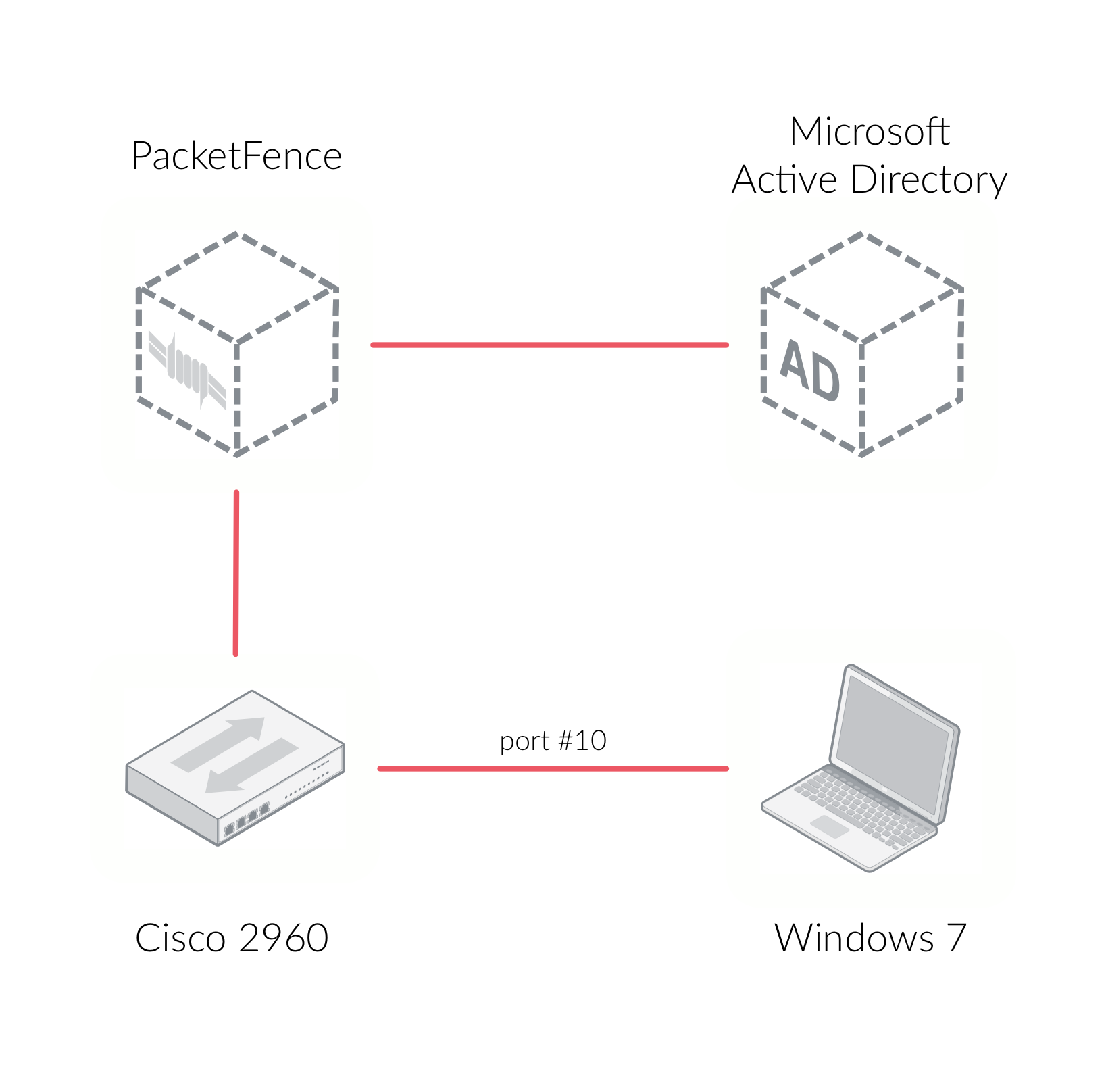
This section configures PacketFence as a RADIUS server with 802.1X support through Microsoft Active Directory and a Cisco 2960 access switch. The 802.1X client is a Microsoft Windows 7 computer connected to the Cisco 2960 switch. The architecture diagram shows component interconnections:
5.1. Going Through the Configurator
Open PacketFence’s configurator at https://@ip_of_packetfence:1443. If unsure of
the IP address, run ip a in Linux shell. Complete these steps:
- Step 1 - Configure Network - Define one interface with "Management" type. This interface connects to the Cisco 2960 access switch. The management interface and Cisco 2960 should be on the same network. Click the logical name to edit interface type
- Step 2 - Configure PacketFence - Provide required information for PacketFence database creation, domain name, hostname and admin credentials
- Step 3 - Fingerbank - Provide Fingerbank API key. Fingerbank identifies IoT devices, medical devices, industrial and robotics equipment. An API key is recommended for device profiling
- Step 4 - Confirmation - save the passwords in a secure location and start PacketFence!
After services start, the system redirects to PacketFence’s admin interface at https://@ip_of_packetfence:1443/. Log in using credentials from Step 2.
5.2. Connecting PacketFence to Microsoft Active Directory
Join PacketFence to the Microsoft Active Directory domain. From the admin
interface, go to Configuration → Policies and Access Control → Domains →
Active Directory Domain and click New domain. Provide required fields
including domain admin credentials. Click Create & Join.
After successful domain join, click the REALMS tab. Set the Default realm to
use the new Active Directory domain. Repeat for the NULL realm.
Add Microsoft Active Directory as an authentication source. From Configuration
→ Policies and Access Control → Authentication Sources, click New internal
source → AD. Specify required fields. Use Active Directory Explorer or
AdsiEdit.mmc tools for field identification.
In this new Authentication Source, add an Authentication Rules with name
catchall with no condition and with the following actions:
- Role - default
- Access duration - 5 days
Make sure the information you provided are valid. Click on the Test button to
validate the provided information. If you see the message Success! LDAP connect,
bind and search successful - the Microsoft Active Directory authentication
source has been properly configured. Save the new authentication
source by clicking on the Save button.
5.3. Configuring Cisco Catalyst 2960 Switch
Next, we configure a switch so that it integrates with PacketFence using 802.1X. In our example, we will use a Cisco Catalyst 2960 access switch and its IP address will be 172.21.2.3. Our PacketFence’s server IP address will be 172.20.100.2 - adjust this according to the environment.
Connect to that switch over SSH as an admin.
5.3.1. Enable 802.1X
As a first configuration step, enable 802.1X globally on the switch. Use the following:
dot1x system-auth-control
5.3.2. Configure AAA
The next step is to configure AAA so it will use the newly created PacketFence server. Replace the PF_MANAGEMENT_IP variable with the actual PacketFence management IP (172.20.100.2 in this example) in the following commands:
aaa new-modelaaa group server radius packetfenceserver PF_MANAGEMENT_IP auth-port 1812 acct-port 1813aaa authentication login default localaaa authentication dot1x default group packetfenceaaa authorization network default group packetfenceradius-server host PF_MANAGEMENT_IP auth-port 1812 acct-port 1813 timeout 2key useStrongerSecretradius-server vsa send authenticationsnmp-server community public ROsnmp-server community private RW
5.3.3. Configure Switchport for 802.1X
Once AAA is ready, configure some or all switchports to perform 802.1X. In this example, only configure port no. 10 to use 802.1X:
interface fastEthernet 0/10switchport mode accessauthentication host-mode single-hostauthentication order dot1x mabauthentication priority dot1x mabauthentication port-control autoauthentication periodicauthentication timer restart 10800authentication timer reauthenticate 10800mabno snmp trap link-statusdot1x pae authenticatordot1x timeout quiet-period 2dot1x timeout tx-period 3
Write the switch configuration to memory.
5.4. Adding the Switch to PacketFence
PacketFence must be aware of the equipment it manages. From Configuration →
Policies and Access Control → Network Devices → Switches, click on New
Switch → default. Enter the switch IP address (172.21.2.3 in our example). As
a switch type, select Cisco Catalyst 2960 and select Production as the Mode.
From the Roles tab, make sure Role by VLAN ID is checked and that the VLAN
ID associated to the default role is set to the normal VLAN currently in use on
the network. In our example, it will be VLAN 20. That means that once a 802.1X
authentication is allowed by PacketFence, access will be properly granted in the
default role in VLAN 20.
From the RADIUS tab, specify the Secret Passphrase to use - in our example,
it is useStrongerSecret. It is very important to correctly set the RADIUS
secret passphrase otherwise PacketFence will prevent the switch from
communicating to itself.
Finally, from the SNMP tab, provide the correct Community Read and
Community Write values.
5.5. Configuring the Connection Profile
Next, configure the connection profile in PacketFence. That is required so that PacketFence knows how to handle a connection coming from the wired network or WiFi network. In this case, create a new connection profile to use the Microsoft Active Directory authentication source and notify PacketFence to automatically register any devices that successfully authenticate using 802.1X on the default connection profile.
From Configuration → Policies and Access Control → Connection Profiles,
click on on New Connection Profile. Specify the following information:
- Profile Name: 8021x
- Profile Description: 802.1X wired connections
- Enable profile: checked
- Automatically register devices: checked
-
Filters: If any of the following conditions are met:
- Connection Type: Ethernet-EAP
- Sources: the newly created Active Directory authentication source
Click on Create to save all configuration changes.
5.6. Configuring Microsoft Windows Supplicant
To enable 802.1X on the wired adapter of the Microsoft Windows 7 endpoint,
first enable the Wired AutoConfig service. From the
Microsoft Windows Services control panel, double-click on Wired AutoConfig.
Make sure Startup type: is set to Automatic and click on Start to enable
the service.
Then, from Windows` Network Connection panel, open the Properties window of the
LAN interface you will use for testing. From the authentication tab, make sure
Enable IEEE 802.1X
authentication
is checked. As the authentication method,
make sure Microsoft: Protected EAP (PEAP) is selected. Then, click on
Settings and make sure Validate server certificate is unchecked. As
authentication method, make sure Secured password (EAP-MSCHAPv2) is selected.
Then, click on Configure … and make sure Automatically use my Windows logon
name and password (and domain if any) is unchecked.
Save all changes.
5.7. Testing
Now, perform the testing. First restart the radiusd
service. This is required since a new Active Directory domain
controller was added. From Status → Services, click on the Restart button for the
radiusd service. PacketFence will take care of restarting that service and the
radiusd-acct and radiusd-auth sub-services.
Connect the Microsoft Windows 7 endpoint on port no. 10 from the Cisco Catalyst 2960 switch. From Microsoft Windows, a popup should appear prompting you for a username and password. Enter a valid username and password from the Microsoft Active Directory domain - this should trigger 802.1X (EAP-PEAP) authentication.
To see what’s happening in PacketFence, click on the Auditing tab from
PacketFence’s admin interface. An entry should appear for the MAC address of
the Microsoft Windows 7 endpoint. Click on the line with the correct MAC address
to see the RADIUS exchanges. If the 802.1X authentication is successful, Accept appears as the Auth Status.
If authentication fails or you don’t see RADIUS entries, see RADIUS Debugging and RADIUS Audit Log in the Troubleshooting section.
5.8. Alerting
PacketFence can send emails to administrators, users and guests. Therefore, it is important to properly configure the mail sending functionality of PacketFence. From Configuration → System Configuration → Alerting, set at least the following fields:
- Sender - the "From" address of emails being sent by PacketFence
- SMTP server - IP or DNS name of the SMTP server used by PacketFence to send all emails
If the SMTP server requires authentication or encryption to relay emails, properly configure the SMTP encryption, username and password parameters.
6. Enabling the Captive Portal
In the previous section, we have successfully configured 802.1X using PacketFence, Microsoft Active Directory and a Cisco Catalyst 2960 switch. While this demonstrates the fundamental role and capabilities of a NAC solution, most organizations are also looking at providing access to guests for example. One way of handling guests on a network is showing them a captive portal and let them register their own devices. This section will guide you in achieving this with PacketFence.
There are two ways PacketFence can show its captive portal for unknown (or unregistered) devices:
- it can use Web Authentication (or also known as hotspot-style authentication) - this works with numerous equipment vendors
- it can use a registration VLAN, where PacketFence provides DHCP services and DNS black-holing services - this works with any equipment vendors that support RADIUS dynamic VLAN assignment
For our example, we will use Web Authentication, as it is supported by the Cisco
Catalyst 2960. For more information on various enforcement modes, please refer
to the Supported Enforcement Modes sections of this document.
6.1. Creating Authentication Source for Guests
To keep our example simple, we will simply create a captive portal for guests
where they will only have to accept the terms and conditions prior to gaining
network access. To do so, we must first create a Null authentication source.
From Configuration → Policies and Access Control → Authentication Sources,
click on New external source → Null. As Name and Description, specify
'null-source'. Then add an Authentication Rules with name catchall with no
condition and with the following tow Actions:
- Role - guest
- Access duration - 12 hours
Click on Save to save the new authentication source.
6.2. Configure switchport for Web Authentication
Connect to that switch over SSH as an admin.
First, we need to enable Change-of-Authorization (CoA) in our Cisco Catalyst 2960 switch configuration. We essentially need to allow our PacketFence server (172.20.100.2) to send CoA requests to the switch:
aaa server radius dynamic-authorclient 172.20.100.2 server-key useStrongerSecretport 3799
Then, we must enable Web Authentication on switch port no. 10. Add the following configuration to the global section:
ip device trackingip http serverip http secure-server
Then add the required access list:
ip access-list extended registrationdeny ip any host 172.20.100.2permit tcp any any eq wwwpermit tcp any any eq 443
6.3. Adjust Switch Configuration in PacketFence
Next we have to let PacketFence know that Web Auth is to be used on the Cisco
Catalyst 2960 switch. From Configuration → Policies and Access Control →
Switches and click on the switch’s IP to open its configuration options. From
the Definition tab, make sure Use CoA and External Portal Enforcement are
checked and set the CoA Port to 3799. From the Roles tab, make the following
changes:
- in Role by VLAN ID, set the registration and guest VLAN ID to 20 - this will ensure unregistered clients are initially put in VLAN 20 and avoid a VLAN change once they properly authenticate from the captive portal
-
make sure
Role by Switch Roleis checked and set the registration role toregistration- this will ensure the registration access list created in the previous section is returned for unregistered users. This will limit their access to the PacketFence captive portal -
make sure
Role by Web Auth URLis checked and set theregistrationURL tohttp://172.20.100.2/Cisco::Catalyst_2960
Click on Save to save all configuration changes.
6.4. Enabling Portal on Management Interface
By default the PacketFence’s captive portal does not listen on the management
interface. To change this, go in Configuration → Network Configuration →
Interfaces and click on the logical name of the management interface to bring
the configuration panel. In Additionnal listening daemon(s) - make sure you
add portal.
You must then restart the following services from Status → Services:
- haproxy-portal
- httpd.portal
6.5. Configuring the Connection Profile
For Web Authentication, we will create a new connection profile in PacketFence.
That means the default connection profile will be used for 802.1X while the new
connection profile will be used for Web Authentication and will be used to
display a captive portal with our Null authentication source. From
Configuration → Policies and Access Control → Connection Profiles click on
New Profile. Specify the following information:
- Profile Name: guest
- Filters: If any of the following conditions are met:
- Connection Type: Ethernet-NoEAP
- Sources: null-source
Click on Save to save all configuration changes.
6.6. Testing
First make sure that the Microsoft Windows 7 endpoint is unplugged from the
Cisco Catalyst 2960 switch. Then, make sure the endpoint is unregistered from
PacketFence. To do this, from the Nodes configuration module, locate its MAC
address and click on it. From the node property window, change the Status to
unregistered.
Next, we need to disable 802.1X from the network configuration card from the
Microsoft Windows 7 endpoint. We want to simulate here an authentication by MAC
address, so we have to disable 802.1X to do this. From Windows` Network
Connection connection panel, ask for the properties of the LAN interface you
will use for testing. From the authentication tab, make sure Enable IEEE 802.1X
authentication is unchecked. Save all changes.
Next, connect the endpoint in the Cisco Catalyst 2960 switch. After a few second, open a web browser and try to open any website - say https://www.packetfence.com. You should now see the captive portal. You should only need to accept the terms and conditions for gaining network access.
If the captive portal doesn’t appear or redirects fail, check portal-related logs as described in Log Files and Network Connectivity Issues in the Troubleshooting section.
7. Authentication Sources
PacketFence authenticates users registering devices via captive portal using various methods:
- Active Directory
- Apache htpasswd file
- BlackHole
- External HTTP API
- Clickatell
- Facebook (OAuth 2)
- Github (OAuth 2)
- Google (OAuth 2)
- Kerberos
- Kickbox
- LDAP
- LinkedIn (OAuth 2)
- Null
- OpenID Connect (OAuth 2)
- RADIUS
- SMS
- Sponsored Email
- Twilio
- Windows Live (OAuth 2)
- Password of the day
and many others. PacketFence also authenticates users in its internal SQL
database. Create authentication sources from the admin interface: Configuration
→ Policies and Access Control → Authentication Sources. Authentication
sources, rules, conditions and actions stored in
/usr/local/pf/conf/authentication.conf.
Each authentication source has rules, conditions and actions.
Multiple authentication sources are tested in specified order (reorder in admin interface by dragging). Each source can have multiple rules, tested in order. Rules can be reordered like sources. Conditions define rule matching criteria. When criteria match, actions apply and rule testing stops across all sources ("first match wins").
When no condition is defined, the rule will be considered as a catch-all. When a catch-all is defined, all actions will be applied for any users that match in the authentication source. Once a source is defined, it can be used from Configuration → Policies and Access Control → Connection Profiles. Each connection profile has a list of authentication sources to use.
In the previous section, you configured two authentication sources: Microsoft Active Directory and the Null sources. They were both catch-all sources.
7.1. Email Authentication for Guests
This section will show you how to allow guests to register endpoints using their email address. PacketFence sends a PIN code to the guest’s email address. That code will then be required to complete the registration process.
7.1.1. Adding Email Authentication Source
From Configuration → Policies and Access Control → Authentication Sources,
click New external source → Email. As Name and Description, specify
email-source.
Additional options available
- email_activation_timeout - This is the delay given to a guest who registered by email confirmation to log into his email and click the activation link.
- allow_localdomain - Accept self-registration from email address within the local domain
- activation_domain - Set this value if you want to change the hostname in the validation link. Changing this requires to restart haproxy to be fully effective.
- allowed_domains - A comma-separated list of domains that are allowed for email registration. Allowed domains are checked after banned domains.
- banned_domains - A comma-separated list of domains that are banned for email registration. Banned domains are checked before allowed domains.
Then add an Authentication Rules with name catchall with no condition and
with the following two Actions:
- Role - guest
- Access duration - 12 hours
Click on Create to save the new authentication source.
7.1.2. Configuring the Connection Profile
Now let’s add our new Email-based authentication source to our guests captive
portal. From Configuration → Policies and Access Control → Connection
Profiles, click on the guest profile that we previously created. In the
Sources, click on the (+) button and add the newly created Email source,
email-source. Save the changes by clicking on the Save button.
Preview button near the Connexion’s title.7.1.3. Testing
Unplug and unregister your endpoint. Reconnect the endpoint - you should see the captive portal with the new Email-based registration option.
7.2. Adding SMS Authentication for Guests
This section will show you how to enable SMS authentication on the captive portal so that guests use their cellular phone number to register their endpoints. PacketFence will send an SMS PIN code to the guest phone number. That code will be required to complete the registration process. The SMS code will be sent by PacketFence over email - using popular SMTP-to-SMS gateways.
Some of the key concepts presented in this section are:
- Authentication sources
7.2.1. Adding SMS Authentication Source
Now that you understand what authentication sources and alerting are, we will add an SMS authentication source on our guest portal. We previously used the 'Null` source but we will add another source. Portal profiles can provide multiple authentication sources.
From Configuration → Policies and Access Control → Authentication Sources,
click New external source → SMS. As Name and Description, specify
sms-source. Then add an Authentication Rules with name catchall with no
condition and with the following two Actions:
- Role - guest
- Access duration - 12 hours
You will also need to select the proper carriers to do your test. Make sure you include the one your are using for your cellular phone.
Click on Create to save the new authentication source.
Clickatell Source
To use Clickatell as an SMS source, first register at https://www.clickatell.com
to get an API Key for the SMS integration. Then add it as an authentication
source the same way as above, except choosing Clickatell instead of SMS in
Add source → External. Enter a name, description and your Clickatell API key
in the source configuration, then add the authentication rule.
7.2.2. Configuring the Connection Profile
Now let’s add our new SMS-based authentication source to our guests captive
portal. From Configuration → Policies and Access Control → Connection
Profiles, click on the guest profile that we previously created. In the
Sources, click on the (+) button and add the newly created SMS source,
sms-source. Save the changes by clicking on the Save button.
Preview button near the Connexion’s title.7.2.3. Testing
First unplug and unregister again the Microsoft Windows 7 endpoint. Then, connect the endpoint in switch port no. 10 - you should see the captive portal with the new SMS-based registration option. Note that the Null option will also be offered.
7.3. Troubleshooting Authentication Issues
For authentication troubleshooting, see Authentication Failures, Log Files, and RADIUS Debugging in the Troubleshooting section.
8. Introduction to Role-based Access Control
One important key concept from NAC solutions is for segregating network accesses. For example, an employee from the finance department might not have the same network access level as another employee from the marketing department. Guests should also not have the same access level as normal employees within an organization. PacketFence uses roles internally to identify and differentiate users. For segregating network access, PacketFence can use one or all of the following techniques:
- ACL
- VLAN or VLAN pool
- equipment role
The techniques to use depend on the wired/WiFi equipment itself. A role in PacketFence will be eventually mapped to a VLAN, an ACL or an external role. Define the roles to use in the organization for network access.
In our previous configuration examples, we made use of two roles that come by default in PacketFence: default and guest. We will now add two new roles - one for consultants and one used to authenticate machines on the network.
8.1. Adding Roles
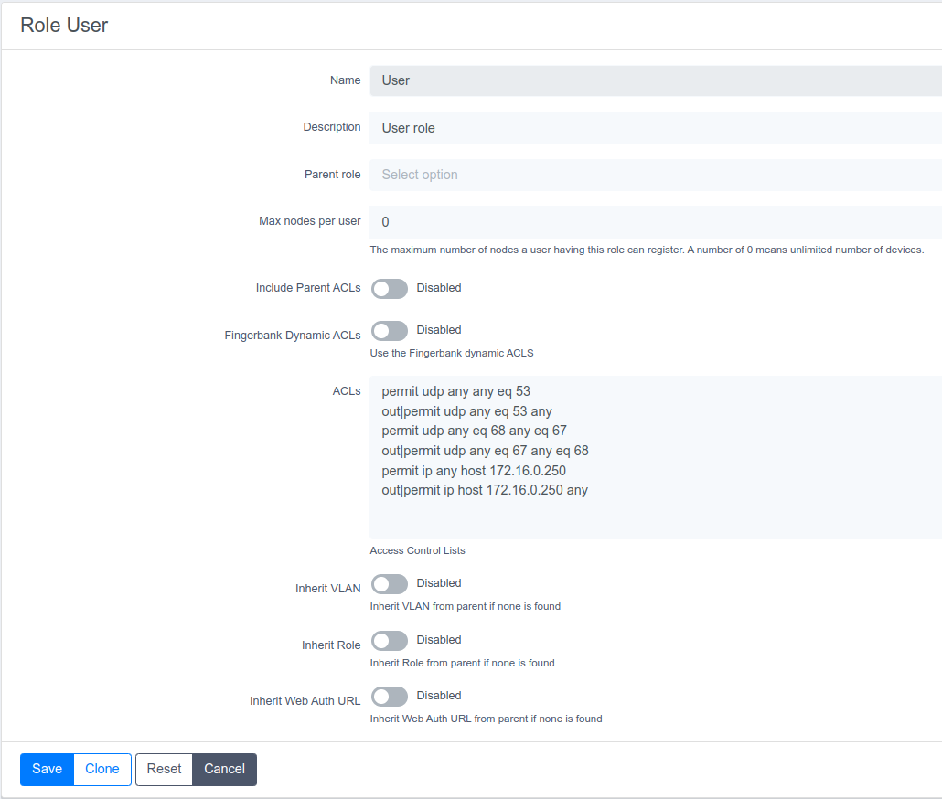
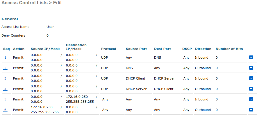
Roles in PacketFence can be created from Configuration → Policies and Access Control → Roles. From this interface, limit the number of devices users belonging to certain roles can register.
Roles are dynamically computed by PacketFence, based on the rules (ie., a set of conditions and actions) from authentication sources, using a first-match wins algorithm. Roles are then matched to VLAN or VLAN pool or internal roles or ACL on equipment from the Configuration → Policies and Access Control → Switches module. For a VLAN pool instead of defining a VLAN identifier, set a value like that: 20..23,27..30 - which means that the VLAN returned by PacketFence can be 20 to 23 and 27 to 30 (inclusively). There are three algorithms: one based on a hash of the username (default one), another one based on a round-robin (last registered device +1) and one that selects a VLAN randomly in the pool.
Configuration → Policies and Access Control → Roles, click on New Role.
Provide the following information:
- Name: employee
- Description: Role used for employees
- Max nodes per user: 2
Redo the operation of the other role:
- Name: corporate_machine
- Description: Corporate owned machines
- Max nodes per user: 1
Let’s say we have two roles: employee and corporate_machine (defined above).
Now, we want to assign roles to employees and their corporate machines using Active Directory (over LDAP), both using PacketFence’s captive portal.
8.2. Using the Employee Role
From the Configuration → Policies and Access Control → Authentication
Sources, we select New internal source → AD. We provide the following
information:
- Name: ad1
- Description: Active Directory for Employees
- Host: 192.168.1.2:389 without SSL/TLS
- Base DN: CN=Users,DC=acme,DC=local
- Scope: subtree
- Username Attribute: sAMAccountName
- Bind DN: CN=Administrator,CN=Users,DC=acme,DC=local
- Password: acme123
Then, we add an Authentication rules by clicking on the Add rule button and
provide the following information:
- Name: employees
- Description: Rule for all employees
- Don’t set any condition (as it’s a catch-all rule)
- Set the following actions:
- Role - employee
- Access duration - 7 days
Test the connection and save everything. Using the newly defined source, any username that actually matches in the source (using the sAMAccountName) will have the employee role and a 7 days Access Duration.
8.3. Using the Corporate_Machine Role
To differentiate user authentication and machine authentication using Active Directory, create a second authentication sources, for machines:
- Name: ad2
- Description: Active Directory for Corporate Machines
- Host: 192.168.1.2:389 without SSL/TLS
- Base DN: CN=Computers,DC=acme,DC=local
- Scope: One-level
- Username Attribute: servicePrincipalName
- Bind DN: CN=Administrator,CN=Users,DC=acme,DC=local
- Password: acme123
Then, we add an Authentication rules:
- Name: machines
- Description: Rule for corporate machines
- Don’t set any condition (as it’s a catch-all rule)
- Set the following actions:
- Role - corporate_machine
- Access duration - 7 days
Using this configuration, employees can only connect corporate machines, not personal devices.
9. Supported Enforcement Modes
Choose appropriate enforcement mode before configuring PacketFence. Enforcement mode is the technique used to enforce device registration and network access. PacketFence supports these enforcement modes:
- Inline
- Out-of-band using SNMP or RADIUS
- Hostpot-style (or Web Auth)
- RADIUS only
- DNS
Enforcement modes can be combined. For example, use out-of-band mode on wired switches and inline mode on older WiFi access points.
Following sections explain these enforcement modes and PacketFence configuration for each.
9.1. Technical Introduction to Inline Enforcement
9.1.1. Introduction
Many NAC solutions cannot support unmanageable devices like entry-level consumer switches or access-points. PacketFence inline mode supports these devices in-band. PacketFence becomes the gateway for the inline network, using IPTables/IPSet to NAT or route traffic to the Internet or other network sections.
9.1.2. Device Configuration
No special configuration needed on unmanageable devices. Simply ensure the device communicates on the inline VLAN. All traffic passes through PacketFence as it serves as the VLAN gateway.
9.1.3. Access Control
Access control relies entirely on IPTables/IPSet. When unregistered users connect to inline VLAN, PacketFence assigns IP addresses. Users are marked as unregistered in ipset session - web traffic redirects to captive portal, other traffic is blocked. After registration through captive portal (like VLAN enforcement), PacketFence updates the device’s ipset session to allow the user’s MAC address through.
9.1.4. Limitations
Inline enforcement has several limitations due to its nature:
- Everyone behind an inline interface is on the same Layer 2 LAN
- Every packet of authorized users goes through the PacketFence server increasing the server’s load considerably: Plan ahead for capacity
- Every packet of authorized users goes through the PacketFence server: it is a single point of failure for Internet access
- Ipset can store up to 65536 entries, so it is not possible to have an inline network class greater than a class B
This is why it is considered a poor man’s way of doing access control. We have avoided it for a long time because of the above mentioned limitations. That said, being able to perform both inline and VLAN enforcement on the same server at the same time is a real advantage: it allows admins to maintain maximum security while they deploy new and more capable network hardware providing a clean migration path to VLAN enforcement.
9.2. Technical Introduction to Out-of-band Enforcement
9.2.1. Introduction
VLAN assignment is currently performed using several different techniques. These techniques are compatible one to another, but not on the same switch port. This means that you can use the more secure and modern techniques for your latest switches and another technique on the old switches that doesn’t support latest techniques. As it’s name implies, VLAN assignment means that PacketFence is the server that assigns the VLAN to a device. This VLAN can be one of your VLANs or it can be a special VLAN where PacketFence presents the captive portal for authentication or remediation.
VLAN assignment effectively isolate your hosts at the OSI Layer2 meaning that it is the trickiest method to bypass and is the one which adapts best to your environment since it glues into your current VLAN assignment methodology.
9.2.2. VLAN assignment techniques
Wired: 802.1X + MAC Authentication
802.1X provides port-based authentication, which involves communications between a supplicant, authenticator (known as NAS), and authentication server (known as AAA). The supplicant is often software on a client device, such as a laptop, the authenticator is a wired Ethernet switch or wireless access point, and the authentication server is generally a RADIUS server.
The supplicant (i.e., client device) is not allowed access through the authenticator to the network until the supplicant’s identity is authorized. With 802.1X port-based authentication, the supplicant provides credentials, such as user name / password or digital certificate, to the authenticator, and the authenticator forwards the credentials to the authentication server for verification. If the credentials are valid (in the authentication server database), the supplicant (client device) is allowed to access the network. The protocol for authentication is called Extensible Authentication Protocol (EAP) which have many variants. Both supplicant and authentication servers need to speak the same EAP protocol. Most popular EAP variant is PEAP-MsCHAPv2 (supported by Windows / Mac OSX / Linux for authentication against AD).
In this context, PacketFence runs the authentication server (a FreeRADIUS instance) and will return the appropriate VLAN to the switch. A module that integrates in FreeRADIUS does a remote call to the PacketFence server to obtain that information. More and more devices have 802.1X supplicant which makes this approach more and more popular.
MAC Authentication is a new mechanism introduced by some switch vendor to handle the cases where a 802.1X supplicant does not exist. Different vendors have different names for it. Cisco calls it MAC Authentication Bypass (MAB), Juniper calls it MAC RADIUS, Extreme Networks calls it Netlogin, etc. After a timeout period, the switch will stop trying to perform 802.1X and will fallback to MAC Authentication. It has the advantage of using the same approach as 802.1X except that the MAC address is sent instead of the user name and there is no end-to-end EAP conversation (no strong authentication). Using MAC Authentication, devices like network printer or non-802.1X capable IP Phones can still gain access to the network and the right VLAN.
Wireless: 802.1X + MAC authentication
Wireless 802.1X works like wired 802.1X and MAC authentication is the same as wired MAC Authentication. Where things change is that the 802.1X is used to setup the security keys for encrypted communication (WPA2-Enterprise) while MAC authentication is only used to authorize (allow or disallow) a MAC on the wireless network.
On wireless networks, the usual PacketFence setup dictate that you configure two SSIDs: an open one and a secure one. The open one is used to help users configure the secure one properly and requires authentication over the captive portal (which runs in HTTPS).
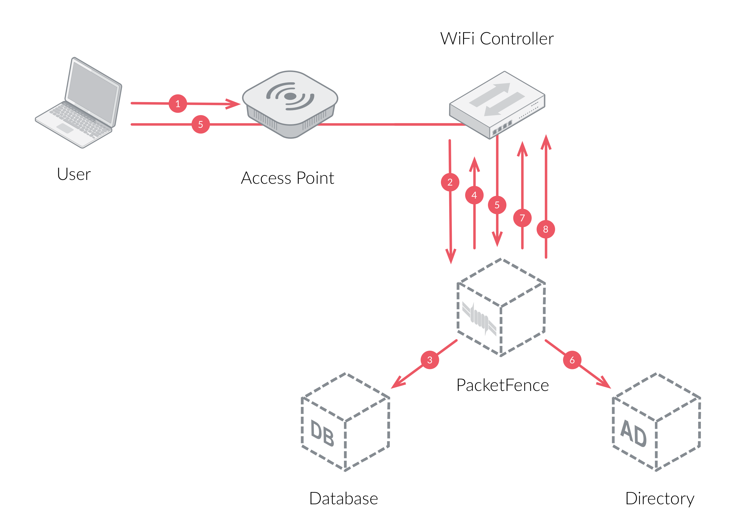
The following diagram demonstrates the flow between a mobile endpoint, a WiFi access point, a WiFi controller and PacketFence:
-
User initiates association to WLAN AP and transmits MAC address. If user accesses network via a registered device in PacketFence, go to step 8.
-
The WLAN controller transmits MAC address via RADIUS to the PacketFence server to authenticate/authorize that MAC address on the AP.
-
PacketFence server conducts address audit in its database. If it does not recognize the MAC address, go to step 4. If it does, go to step 8.
-
PacketFence server directs WLAN controller via RADIUS (RFC2868 attributes) to put the device in an "unauthenticated role“ (set of ACLs that would limit/redirect the user to the PacketFence captive portal for registration, or we can also use a registration VLAN in which PacketFence does DNS blackholing and is the DHCP server).
-
The user’s device issues a DHCP/DNS request to PacketFence (which is a DHCP/DNS server on this VLAN or for this role) which sends the IP and DNS information. At this point, ACLs are limiting/redirecting the user to the PacketFence’s captive portal for authentication. PacketFence fingerprints the device (user-agent attributes, DHCP information & MAC address patterns) to which it can take various actions including: keep device on registration portal, direct to alternate captive portal, auto-register the device, auto-block the device, etc. If the device remains on the registration portal the user registers by providing the information (username/password, cell phone number, etc.). At this time PacketFence could also require the device to go through a posture assessment (using Nessus, OpenVAS, etc.).
-
If authentication is required (username/password) through a login form, those credentials are validated via the Directory server (or any other authentication sources - like LDAP, SQL, RADIUS, SMS, Facebook, Google+, etc.) which provides user attributes to PacketFence which creates user+device policy profile in its database.
-
PacketFence performs a Change of Authorization (RFC3576) on the controller and the user must be re-authenticated/reauthorized, so we go back to step 1.
-
PacketFence server directs WLAN controller via RADIUS to put the device in an "authenticated role“, or in the "normal" VLAN.
Web Authentication Mode
Web authentication is a method on the switch that forwards HTTP traffic of the device to the captive portal. With this mode, your device will never change of VLAN ID but only the ACL associated to your device will change. Refer to the Network Devices Configuration Guide to see a sample web auth configuration on a Cisco WLC.
Downloadable ACLs
Downloadable ACLs is a method that can be used when the ACL list is greater than the size of a RADIUS access-accept paquet. Some vendor support it, like Cisco Switches (IOS 15.2) and Dell (n1500 fw 6.8)
The RADIUS flow is something close to the normal one but in the Access-Accept reply there is an extra RADIUS attribute for the equipment to trigger another RADIUS request to retrieve the ACL.
A second RADIUS request is made with the ACL name as a value of the username and multiples Access-Challenge are made to retrieve the complete ACL.
To enable it you need first to enable the RADIUS filter in the PacketFence
authorize section. To do that go in Configuration → System Configuration →
RADIUS → General and enable Use RADIUS filters in packetfence authorize then
restart service radiusd-auth.
/usr/local/pf/bin/pfcmd service radiusd-auth restart
Push ACLs
Push ACLs is a method to write directly the ACLs on the equipment if compatible
(needs ssh credentials and admin privileges on the switch).
In this senario if the PushACLs is enable on the switch then PacketFence will
take the ACL defined in each role configuration (Policies and Access Control →
Roles, and ACL in Cisco format), format it to be compatible with the equipment
and will use ansible to push them on the switch (User role will create a User
ACL on the equipment).
Once this ACL is define on the switch, the RADIUS reply will contain an
attribute that tell the switch to apply this ACL on the session.
Per example in the case of Cisco, the attribute used is Filter-ID = User
Role per Switch role needs to be enable and PacketFence will return the role name and not the role value.
Dynamic/Downloadable ACLs can be combined with Push ACLs but in certain conditions. If an ACL is defined in the role in the switch configuration then this one will take precedence on the Push ACL. If the ACL in the role configuration is empty but you have an ACL defined in the role config then PacketFence will only return the attribute to assign the ACL (no RADIUS reply containing the ACL).
Here an example of what happen when you have a Cisco WLC where you enabled PushACLs and you defined the ACL as following:
it will create or replace the User ACL like that:
Port-security and SNMP
Relies on the port-security SNMP Traps. A fake static MAC address is assigned to all the ports this way any MAC address will generate a security violation and a trap will be sent to PacketFence. The system will authorize the MAC and set the port in the right VLAN. VoIP support is possible but tricky. It varies a lot depending on the switch vendor. Cisco is well supported but isolation of a PC behind an IP Phone leads to an interesting dilemma: either you shut the port (and the phone at the same time) or you change the data VLAN but the PC doesn’t do DHCP (didn’t detect link was down) so it cannot reach the captive portal.
Aside from the VoIP isolation dilemma, it is the technique that has proven to be reliable and that has the most switch vendor support.
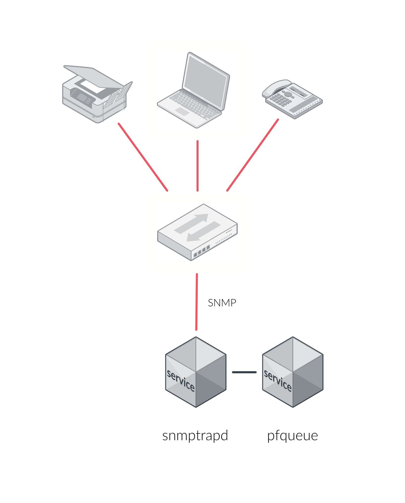
9.2.3. More on SNMP traps VLAN isolation
When the VLAN isolation is working through SNMP traps all switch ports (on which
VLAN isolation should be done) must be configured to send SNMP traps to the
PacketFence host. On PacketFence, we use snmptrapd as the SNMP trap receiver.
As it receives traps, it reformats and sends them into a redis queue, managed by
pfqueue service. The multiprocessed pfqueue service reads these traps from
the redis queue and takes a decision based on type of traps. For example, it can
respond to them by setting the switch port to the correct VLAN. Currently, we
support switches from Cisco, Edge-Core, HP, Intel, Linksys and Nortel (adding
support for switches from another vendor implies extending the pf::Switch
class). Depending on your switches capabilities, pfqueue will act on different
types of SNMP traps.
You need to create a registration VLAN (with a DHCP server, but no routing to other VLANs) in which PacketFence will put unregistered devices. If you want to isolate computers which have open security event in a separate VLAN, an isolation VLAN needs also to be created.
Link Changes (deprecated)
When a host connects to a switch port, the switch sends a linkUp trap to
PacketFence. Since it takes some time before the switch learns the MAC address
of the newly connected device, PacketFence immediately puts the port in the
Registration VLAN in which the device will send DHCP requests in order for the
switch to learn its MAC address. Then pfqueue will send periodical SNMP
queries to the switch until the switch learns the MAC of the device. When the
MAC address is known, pfqueue checks its status (existing ? registered ? any
security event?) in the database and puts the port in the appropriate VLAN. When
a device is unplugged, the switch sends a linkDown trap to PacketFence which
puts the port into the Registration VLAN.
When a computer boots, the initialization of the NIC generates several link
status changes. And every time the switch sends a linkUp and a linkDown trap to
PacketFence. Since PacketFence has to act on each of these traps, this generates
unfortunately some unnecessary load on pfqueue. In order to optimize the trap
treatment, PacketFence stops every thread for a linkUp trap when it receives a
'linkDown` trap on the same port. But using only linkUp/linkDown traps is not
the most scalable option. For example in case of power failure, if hundreds of
computers boot at the same time, PacketFence would receive a lot of traps almost
instantly and this could result in network connection latency.
MAC Notification Traps (deprecated)
If your switches support MAC notification traps (MAC learned, MAC removed), we
suggest that you activate them in addition to the linkUp/linkDown traps. This
way, pfqueue does not need, after a linkUp trap, to query the switch
continuously until the MAC has finally been learned. When it receives a linkUp
trap for a port on which MAC notification traps are also enabled, it only needs
to put the port in the Registration VLAN and can then free the process. When the
switch learns the MAC address of the device it sends a MAC learned trap
(containing the MAC address) to PacketFence.
Port Security Traps
In its most basic form, the Port Security feature remembers the MAC address connected to the switch port and allows only that MAC address to communicate on that port. If any other MAC address tries to communicate through the port, port security will not allow it and send a port-security trap.
If your switches support this feature, we strongly recommend to use it rather than linkUp/linkDown and/or MAC notifications. Why? Because as long as a MAC address is authorized on a port and is the only one connected, the switch will send no trap whether the device reboots, plugs in or unplugs. This drastically reduces the SNMP interactions between the switches and PacketFence.
When you enable port security traps you should not enable linkUp/linkDown nor MAC notification traps.
9.3. Technical Introduction to Hybrid Enforcement
9.3.1. Introduction
In previous versions of PacketFence, it was not possible to have RADIUS enabled for inline enforcement mode. Now with the new hybrid mode, all the devices that supports 802.1X or MAC-authentication can work with this mode. Let’s see how it works.
9.3.2. Device Configuration
You need to configure inline enforcement mode in PacketFence and configure your switch(es) / access point(s) to use the VLAN assignment techniques (802.1X or MAC-authentication). You also need to take care of a specific parameter in the switch configuration window, "Trigger to enable inline mode". This parameter is working like a trigger and you have the possibility to define different sort of triggers:
ALWAYS::PORT::MAC::SSID::
where ALWAYS means that the device is always in inline mode, PORT specify the ifIndex of the port which will use inline enforcement, MAC a mac address that will be put in inline enforcement technique rather than VLAN enforcement and SSID an ssid name. An example:
SSID::GuestAccess,MAC::00:11:22:33:44:55
This will trigger all the nodes that connects to the GuestAccess SSID to use
inline enforcement mode (PacketFence will return a void VLAN or the inlineVlan
if defined in switch configuration) and the MAC address 00:11:22:33:44:55
client if it connects on another SSID.
9.4. Technical Introduction to RADIUS Enforcement
9.4.1. Introduction
The concept of having a RADIUS enforcement is to not use registration,
isolation, nor the portal capabilities of PacketFence. Everything here is for
RADIUS integration only. By default the management interface will be the RADIUS
interface. If needed, it is possible to add another interface from
Configuration → Network Configuration → Networks → Interface. When doing
so, you must select Other as the type of interface. Moreover, you must select
radius as an additionnal listening daemon.
Using RADIUS enforcement, everytime a device connects to the network, a matching production VLAN will be assigned, depending on the rules in Configuration → Policies and Access Control → Authentication Sources.
9.5. Technical Introduction to DNS Enforcement
9.5.1. Introduction
DNS enforcement allows you to control the network access of the device by using
the pfdns service on PacketFence.
The architecture of DNS enforcement is as following :
-
DHCP and DNS are provided by the PacketFence server
- The PacketFence DHCP server will provide the IP of your network equipment as the gateway and the IP address of the PacketFence DNS server to resolve names.
- Routing is provided by another equipment on your network (core switch, firewall, router,…)
-
pfdnswill respond to DNS requests depending on your configuration :- user registration on portal : it will return IP address of the captive portal
- access to another site : it will resolve name externally and use it in reply
This enforcement mode used by itself can be bypassed by the device by using a different DNS server or by using its own DNS cache.
The first can be prevented using an ACL on your routing equipment, the second can be prevented by combining DNS enforcement with Single-Sign-On on your network equipment. Please see the Firewall Single-Sign-On documentation for details on how to accomplish this.
In order to configure DNS enforcement, you first need to go in Configuration → Network Configuration → Networks → Interface then select one of your interfaces and set it in DNS enforcement mode.
After, you must configure a routed network for this interface by clicking New
routed network. See the Routed Networks section of this document for details
on how to configure it.
Once this is done, you must restart the pfdhcp and pfdns services.
10. Adding Inline Enforcement to Existing Installation
10.1. Introduction
The inline enforcement is a very convenient method for performing access control on older network equipment that is not capable of doing VLAN enforcement or that is not supported by PacketFence.
An important configuration parameter to have in mind when configuring inline enforcement is that the DNS reached by these users should be your actual production DNS server - which shouldn’t be in the same broadcast domain as your inline users. The next section shows you how to configure the proper inline interface and it is in this section that you should refer to the proper production DNS.
Inline enforcement uses ipset to mark nodes as registered, unregistered and
isolated.
It is also now possible to use multiple inline interfaces. A node registered on
the first inline interface is marked with an IP:MAC tuple (for L2, only ip for
L3), so when the node tries to register on another inline interface,
PacketFence detects that the node is already registered on the first inline
network. It is also possible to enable inline.should_reauth_on_vlan_change to
force users to reauthenticate when they change inline network - you can change
this from Configuration → Network Configuration → Inline - by checking or
not the Reauthenticate node checkbox.
By default the inline traffic is forwarded through the management network
interface but it is possible to specify another one by adding in
conf/pf.conf the
option interfaceSNAT in inline section of the conf/pf.conf
configuration file.
Alternatively, you can change this from Configuration → Network Configuration
→ Inline in the SNAT Interface section. It is a comma delimited list of
network interfaces like eth0,eth1.2. It’s also possible to specify a network
that will be routed instead of using NAT by adding in
conf/networks.conf an
option nat=no under one or more network sections (take care of the routing
table of the PacketFence server).
10.2. Preparing the Operating System
In order to build an inline deployment of PacketFence setup you need :
- 2 network interfaces for the VM (1 for the Inline and another one to go out)
- a switch port in the management network for the PacketFence server
- a switch port in the inline network for the PacketFence server which needs to be configured in access mode and in the same access VLAN as every switchport on which devices will be connected
10.3. Adding Inline Interface
PacketFence can be configured right from the start using the PacketFence configurator for inline enforcement. In this example, we will continue building on top of our initial deployment by adding a new inline interface to our PacketFence installation.
The first step is to add a dedicated Network Interface Card (NIC) to your
current PacketFence installation. In our example, our new NIC will be named
ens192. The PacketFence web interface will list all currently installed
network interfaces on the system. An IP and a netmask will be visible if the
network interface is configured (either by DHCP or already manually configured).
You can edit those ones, create/delete VLANs on physical interfaces and
enable/disable interfaces. Note that these changes are effective immediately.
Persistence will be written only for enabled interfaces. Which means that if
you change your management IP address, to pursue the configurator, you will need
to go on this new IP address you just set. At all time, you will need to set a
Management interface. That means that the required interface types for inline
enforcement are:
ManagementInline layer 2
Note that PacketFence will provide these services on its inline interface:
- PacketFence provides its own DHCP service. It will take care of IP address distribution in our Inline network. PacketFence will not provide DHCP services on the management network - this is the responsibility of your own infrastructure.
- PacketFence provides its own DNS service. However, for the inline mode, you will also need to provide access to the DNS server of your infrastructure.
In the admin interface, go to Configuration → Network Configuration →
Interfaces, and click on the ens192 logical name. Provide the following
information:
IP Address: 192.168.2.1Netmask: 255.255.255.0Type: Inline Layer 2Additionnal listening daemon(s): portalDNS Servers: 10.0.0.10
Click on Save and toggle the new interface to On.
Once done, PacketFence server should have the following network layout:
Please refer to the following table for IP and subnet information :
| Network Card | Name | Subnet | Gateway | PacketFence Address |
|---|---|---|---|---|
ens160 |
Management |
172.20.100.0/16 |
172.20.0.1 |
172.20.100.2 |
ens192 |
Inline |
192.168.2.0/24 |
192.168.2.1 |
192.168.2.1 |
Finally, from Status→Services, restart the haproxy-portal, pfdhcp,
pfdhcplistener, pfdns services.
10.4. Network Devices
In an inline configuration, the required configurations for network devices (desktops, tablets, printers, etc.) will be to make sure they can all communicate with PacketFence. In other words for a switch you will need to configure every ports on which devices will be connected using the access mode with all of them in the same inline network. Access point will be connected as device to be in the inline subnetwork.
Example with a Cisco switch:
You should be in mode #conf-t if not execute configuration terminal in your
CLI.
interface range [port-range]switchport mode access vlan 1no shutdowninterface [packetfence_ens192]switchport mode access vlan 1no shutdownendcopy running-configuration startup-configuration
Now you can connect any devices that you want to be in the inline network in any of the port you have just configured.
10.5. Adding Connection Profile for Inline
Next thing we do is to add a new connection profile - for devices coming from the inline network. We want to show users the captive portal with our Null authentication sources.
From Configuration → Policies and Access Control → Connection Profiles,
click on
Add Profile. Provide the following information:
- Profile Name: inline
- Filters: If any Network 192.168.2.0/24
- Sources: null-source
Then click on Save.
10.6. Testing the Inline Configuration
You can now test the registration process. In order to do so:
- connect an unregistered device into the switch
-
make sure PacketFence provides an IP address to the device. Look into the
following log file:
/usr/local/pf/logs/packetfence.logor verify on the computer you obtain an IP in the right subnet range
From the computer:
- open a web browser
- try to connect to a HTTP site (eg. http://www.packetfence.com, Not HTTPS)
- make sure that whatever site you want to connect to, you have only access to the registration page.
Register the computer using using the Null authentication source.
Once a computer has been registered:
-
make sure PacketFence changes the firewall (
ipset -L) rules so that the user is authorized through. Look into PacketFence log file:/usr/local/pf/logs/packetfence.log -
from the web administrative interface, go under Nodes and make sure you
see the computer as
Registered. - the computer has access to the network and the Internet.
For inline enforcement issues, check iptables rules and logs as described in Log Files and Network Connectivity Issues in the Troubleshooting section.
11. Adding VLAN Enforcement to Existing Installation
11.1. Introduction
VLAN isolation setup requires:
- Supported switch (consult Network Devices Configuration Guide for vendor types and uplink information)
- Normal, registration and isolation VLANs (VLAN numbers and subnets)
- Switch port for PacketFence server configured as dot1q trunk (multiple VLANs on port)
Network infrastructure assumptions for this configuration:
- VLAN 20 is the management VLAN
- VLAN 102 is the registration VLAN (unregistered devices will be put in this VLAN)
- VLAN 103 is the isolation VLAN (isolated devices will be put in this VLAN)
- VLAN 104 is the normal VLAN (registered devices will be put in this VLAN)
IP and subnet information:
| VLAN ID | VLAN Name | Subnet | Gateway |
|---|---|---|---|
20 |
Management |
172.20.100.0/16 |
172.20.0.1 |
102 |
Registration |
192.168.102.0/24 |
192.168.102.1 |
103 |
Isolation |
192.168.103.0/24 |
192.168.103.1 |
104 |
Normal |
10.0.104.0/24 |
10.0.104.1 |
| VLAN ID | VLAN Name | PacketFence Address | DHCP | DNS |
|---|---|---|---|---|
20 |
Management |
172.20.100.2 |
infrastructure DHCP server |
infrastructure DNS server |
102 |
Registration |
192.168.102.1 |
PF |
PF |
103 |
Isolation |
192.168.103.1 |
PF |
PF |
104 |
Normal |
infrastructure DHCP server |
infrastructure DNS server |
Note that PacketFence will provide these services on its registration and isolation VLANs:
- PacketFence provides its own DHCP services. It will take care of IP address distribution in VLANs 102 and 103. PacketFence will not provide DHCP services on VLAN 104 - this is the responsibility of your own infrastructure
- PacketFence provides its own DNS service. It will take care of naming resolution in VLANs 102 and 103. PacketFence will not provide DNS services on VLAN 104 - this is the responsibility of your own infrastructure
11.2. Adding the Registration, Isolation and Other Interface
First of all, make sure you add a new NIC to your PacketFence server and you set
the switch port where that NIC is connected in trunk. If you prefer, you can
also set your management interface as trunk and set the PVID to your management
VLAN on the switch port where that management is connected.
We will create three interfaces VLAN for registration, isolation and normal using the management interface.
The required interface types for VLAN enforcement are:
- Management
- Registration
- Isolation
- Other
Note that you can only set one (1) management interface.
In our example, we will create three new VLANs on the wired interface on our new
trunk interface (ens224)
To do so, click the Add VLAN button besides the wired interface for each of
the needed VLAN:
Here’s a sample configuration for both of them:
Registration
Virtual LAN ID: 102IP Address: 192.168.102.1Netmask: 255.255.255.0
Isolation
Virtual LAN ID: 103IP Address: 192.168.103.1Netmask: 255.255.255.0
Normal
Virtual LAN ID: 104
According to our example, we’ll associate the correct type the each interfaces.
ens160: Managementens224 VLAN 102: Registrationens224 VLAN 103: Isolationens224 VLAN 104: Other
Make sure that those three interfaces are in an enabled state for the persistence to occur. We also need to set the Default Gateway which will generally be the gateway of the management network.
Finally, from Status→Services, restart the haproxy-portal, pfdhcp,
pfdhcplistener, pfdns services.
11.3. Network Devices
Now let’s modify our switch configuration to enable our new registration and isolation VLANs. In the admin interface, go to Configuration → Policies and Access Control → Network Devices → Switches, and click on our Cisco 2960 switch we added earlier (172.21.2.3).
From the Roles tab, make sure you specify the following information:
Role by VLAN ID: checkedregistration VLAN: 102isolation VLAN: 103default: 104guest: 104
Disable Role by Switch Role and `Role by Web Auth URL'.
Click on the Save button once completed.
11.3.1. Configure the Cisco Catalyst 2960
In previous sections, we correctly configured our switch to do 802.1X. Now let’s slightly modify that configuration so that we enable MAC authentication and 802.1X on a new switch port. This will demonstrate the configuration differences.
11.3.2. Configure Switchport for MAB
Once AAA is ready, we can configure some or all switchports to perform MAB (MAC Authentication Bypass) and 802.1X. In our example, we will only configure port no. 11 without VoIP support:
switchport mode accessauthentication host-mode single-hostauthentication order mab dot1xauthentication priority mab dot1xauthentication port-control autoauthentication periodicauthentication timer restart 10800authentication timer reauthenticate 10800mabno snmp trap link-statusdot1x pae authenticatordot1x timeout quiet-period 2dot1x timeout tx-period 3
If you want to test some ports with a VoIP phone (ex: Voice VLAN 200), add the following lines to your interface configuration:
switchport voice vlan 200authentication host-mode multi-domain
11.3.3. Configure SNMP
Finally, for some operations (like VoIP), PacketFence still need to have SNMP access to the switch. Make sure you configure the two SNMP communities like:
snmp-server community ciscoRead rosnmp-server community ciscoWrite rw
11.3.4. Save the Configuration
When done, don’t forget to save your configuration changes using the write mem
command.
11.4. Adding Connection Profile for Registration
Next thing we do is to add a new connection profile - for devices coming from the registration network. We want to show users the captive portal with our Null authentication sources.
In the admin interface, go to Configuration → Policies and Access Control →
Connection Profiles, and click on Add Profile. Provide the following
information:
- Profile Name: registration
- Filters: If any VLAN 102
- Sources: null-source
Then click on Save.
11.4.1. Testing VLAN Based Enforcement
You can now test the registration process. In order to do so:
- connect an unregistered device into the switch
-
make sure PacketFence receives the radius authentication request from the
switch. Look into the PacketFence log file:
/usr/local/pf/logs/packetfence.log -
make sure PacketFence handles RADIUS requests and sets the switch port to
the registration VLAN (VLAN 102). Look again into PacketFence log file:
/usr/local/pf/logs/packetfence.log
On the computer:
- open a web browser
- try to connect to a HTTP site (eg. http://www.packetfence.com, Not HTTPS)
- make sure that whatever site you want to connect to, you have only access to the registration page.
Register the computer using the Null authentication source.
Once a computer has been registered, make sure:
- PacketFence puts the switch port into the normal VLAN (VLAN 104)
- The computer has access to the network and the Internet.
For VLAN assignment issues, verify switch configuration and trace RADIUS attributes as described in RADIUS Debugging and Network Connectivity Issues in the Troubleshooting section.
12. Authentication Mechanisms
This section covers authentication mechanisms supported by PacketFence. Follow these steps to configure authentication for the captive portal. For PKI integration, refer to the PKI Integration section.
12.1. Microsoft Active Directory (AD)
Go in the Administration interface under Configuration → Policies and Access Control → Domains → Active Directory Domains.
/usr/local/pf/addons/AD/migrate.plClick New Domain and fill in the information about the domain.
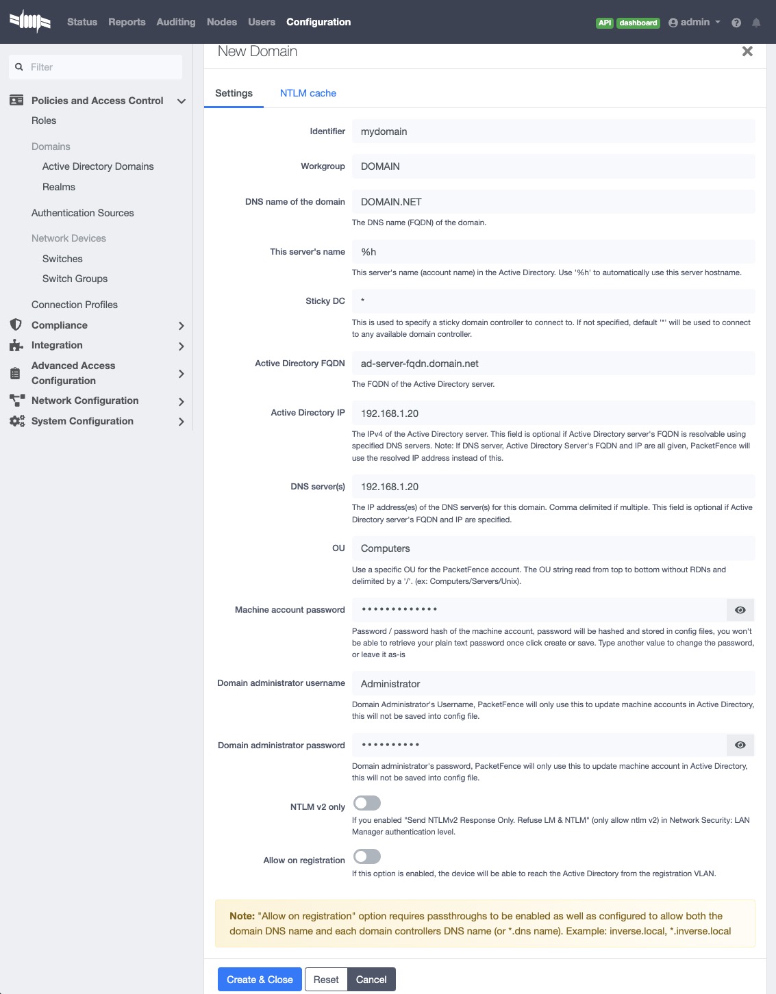
Where :
- Identifier is a unique identifier for the domain. It’s purpose is only visual.
- Workgroup is the workgroup of the domain in the old syntax (like NT4).
- DNS name of the domain is the FQDN of the domain. The one that suffixes the account names.
- This server’s name is the name that the server’s account will have in the Active Directory.
- Sticky DC is the preferred domain controller to connect to.
- Active Directory FQDN FQDN of the Domain Controller.
- Active Directory IP IP Address of the Domain Controller.
- DNS server is the IP address of the DNS server of this domain. Make sure that the server you put there has the proper DNS entries for this domain.
- OU is the OU in the Active Directory where the computer account will be created.
- Machine account password password of server’s account in the Active Directory
- Allow on registration would allow devices in the registration network to communicate with the DC.
- additional machine accounts How many additional machine accounts will be created to handle NTLM authentication. By default 0. Means only 1 machine account will be created. Maximum is 10, you can only create 10 additional machine accounts.
Always check domain settings by running net config workstation on
the domain controller.
form the output,
- Full Computer Name is for Active Directory FQDN,
- Workstation Domain DNS Name is for DNS name of the domain
- Workstation domain is for Workgroup
identifier". If running PacketFence in a cluster, check the corresponding sections for each node.
12.1.1. Domain Joining on A PacketFence cluster (v14.x)
We’ve updated the structure of domain.conf file since v14.0,
the section name stored in domain.conf file has been changed from domain
identifier to hostname + domain identifier combination.
This change causes a node in a cluster to read domain settings from its own
individual section identified by its unique hostname.
Therefore, it is not required to use %h as (or as a prefix / suffix of) the
machine account anymore.
Now it’s technically possible to have fully customized domain settings for a
specific node.
Setting up a new cluster
There’s a difference in domain profile creation for PacketFence cluster running
PacketFence v14.x:
When you create the domain profile from Admin UI for a PacketFence cluster, The
profile is actually created only on the node that handles the API request.
Therefore, go through all the nodes and create a domain profile
for each of them.
During the domain profile creation, a machine account used for NTLM
authentication is also created in Windows domain controller.
Due to the limitation of secure connection binding, we are not able to establish
multiple secure connections using a shared machine account.
Ensure the machine account names are unique if not using %h
as (or as part of) the machine account name.
There are 2 ways of creating the domain profile on a selected node:
- Using API Redirect
- Login into Admin Panel using real IP
To use API Redirect, login into PacketFence Admin Panel, navigate to Status → Services → API redirect, choose a node that handles the API request. And you will create the domain profile for the node you selected.
Login into Admin Panel using real IP is also simple: Login into PacketFence Admin Panel using the node’s real management IP instead of virtual IP. For example, a cluster consists of 3 nodes with a VIP = 192.168.4.70, and real IP = 192.168.4.71, 192.168.4.72, 192.168.4.73. simply iterate the 3 real IPs, login into Admin Panel from https://real_ip:1443.
Upgrade from a version prior to v14.0
If you are doing an upgrade, please refer to the upgrade guide section for v14, you might need to manually combine the domain configuration file and sync them to all cluster members.
Domain config file structure and example
Assuming that we have a PacketFence cluster of 3 nodes with hostnames of
pf-node1, pf-node2 and pf-node3 and we joined "domainA"
an example of domain.conf for a cluster looks like this:
[pf-node1 domainA]ntlm_auth_port=5000server_name=node1dns_name=a.com[....][pf-node2 domainA]ntlm_auth_port=5000server_name=node2dns_name=a.com[...][pf-node3 domainA]ntlm_auth_port=5000server_name=node3dns_name=a.com[...]
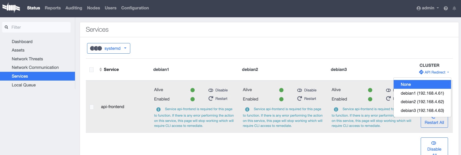
Either the steps will allow you to create the domain profile on the selected node.
After changing the node that handles the API request or choosing the node manually (method 2), do the following steps:
- navigate to "Configuration" → "Policies and Access Control" → "Active Directory Domains"
- fill in the information required to create the domain profile and then click "Create".
- PacketFence will create the domain profile for the node only that handles the API request.
- switch back to API redirect and select another node in the cluster
- back to "Configuration" → "Policies and Access Control" → "Active Directory Domains" and create the domain profile for another node.
- Repeat the previous steps until all the nodes are done with domain profile creation.
12.1.2. Troubleshooting
In order to troubleshoot unsuccessful binds, please refer to the following file : /usr/local/pf/log/packetfence.log. Search for ntlm-auth-api-domain for all ntlm-auth-api entries.
grep "ntlm-auth-api-domain" /usr/local/pf/log/packetfence.log
To check the service status and journal log, use
journalctl -f -u packetfence-ntlm-auth-api-domain@[domain_id]
for domain specific logs. Replace [domain_id] with the domain
To test the authentication process, use the following command
/usr/local/pf/bin/ntlm_auth_wrapper --username=administrator
12.1.3. Default Domain Configuration
Now define the domain to use as the default one by creating the following realm in Configuration → Policies and Access Control → Domains → REALMS.
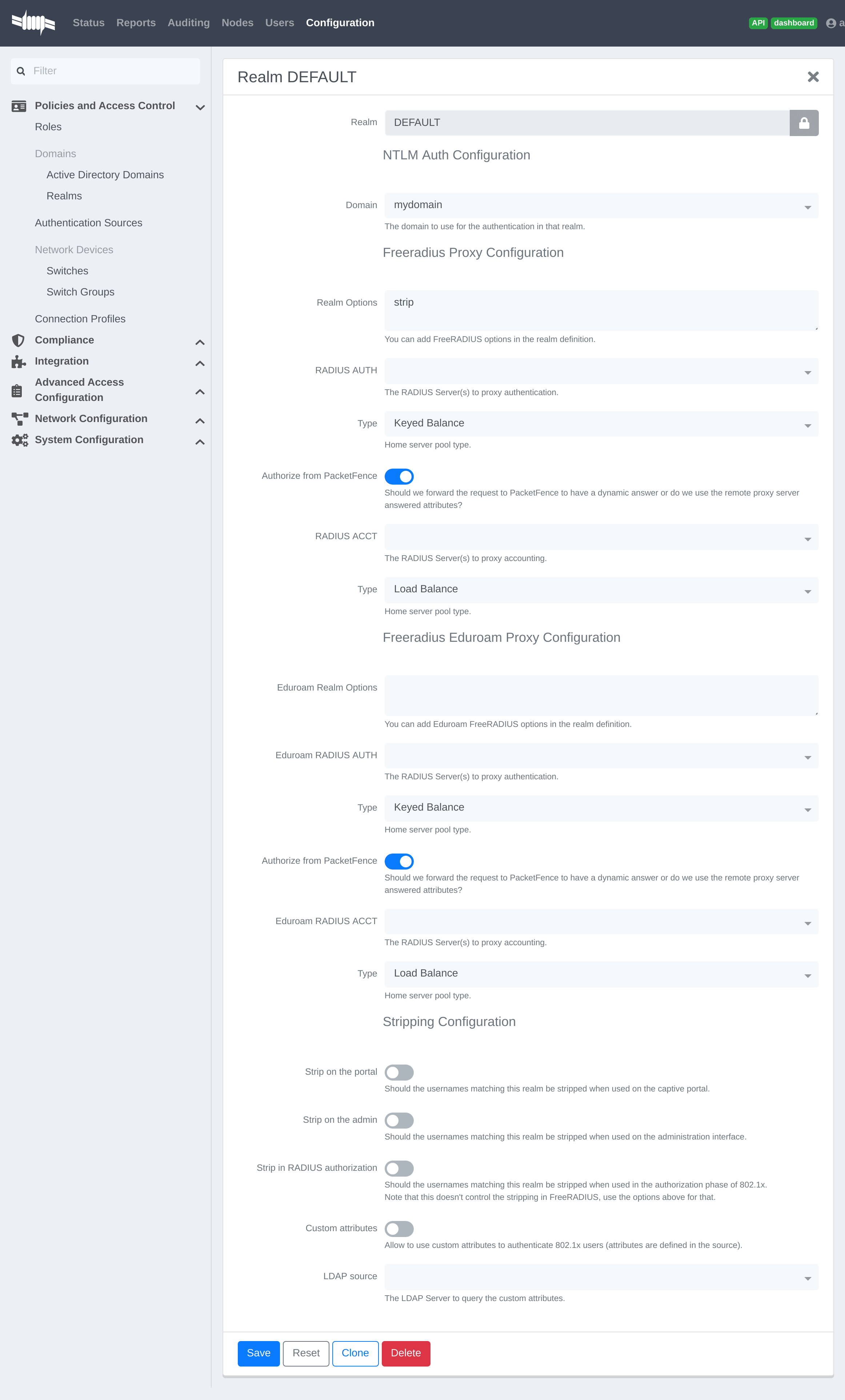
Next, restart PacketFence in Status → Services
12.1.4. Multiple Domains Authentication
First configure the domains in Configuration → Policies and Access Control → Domains → Active Directory Domains.
Once they are configured, go in Configuration → Policies and Access Control → Domains → REALMS.
Create a new realm that matches the DNS name of the domain AND one that matches the workgroup. In the case of this example, it will be DOMAIN.NET tied to mydomain.
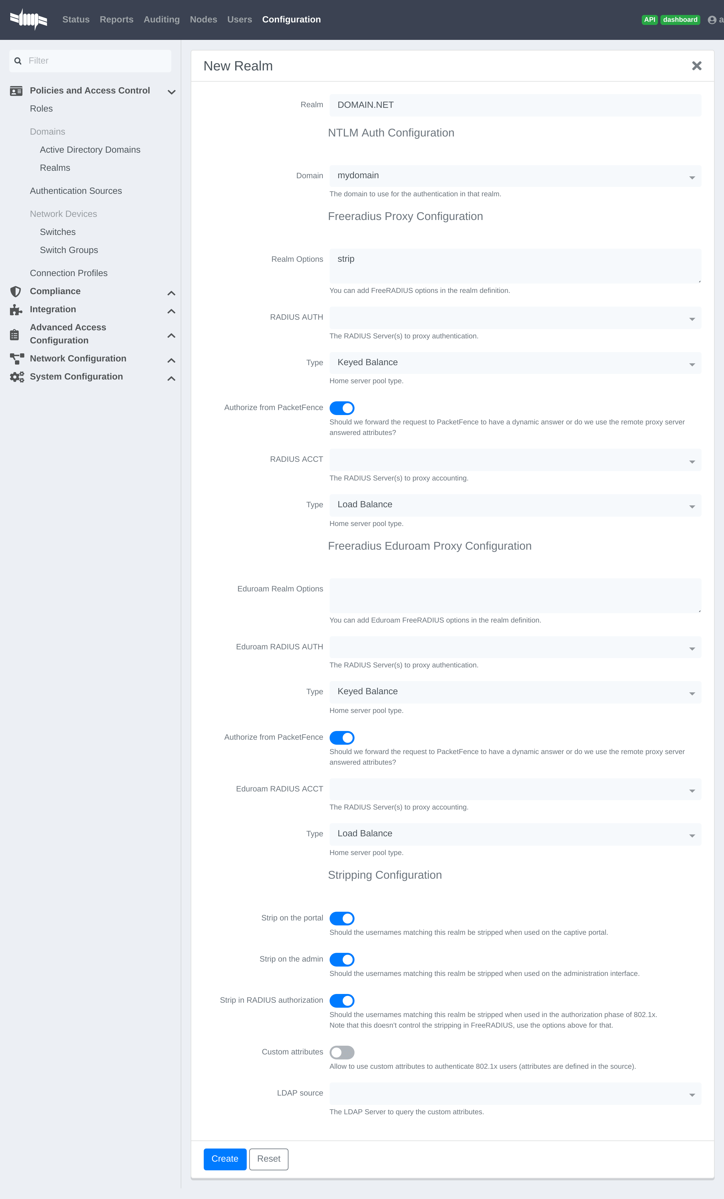
Where :
- Realm is either the DNS name (FQDN) of the domain or the workgroup
- Domain is the Active Directory domain where PacketFence sends the NTLM request
- Realm options are any realm options that you want to add to the FreeRADIUS configuration
- Domain is the domain which is associated to this realm
- RADIUS Auth is the RADIUS authentication server to proxy the request to
- Type is the home server pool type
- Authorize from PacketFence specifies if we forward the request to PacketFence to have a dynamic answer or do we use the remote proxy server answered attributes
- RADIUS Acct is the RADIUS accounting server to proxy the request to
- Type is the home server pool type
- Eduroam Realm Options You can add Eduroam FreeRADIUS options in the realm definition
- Eduroam RADIUS Auth is the RADIUS Eduroam authentication server to proxy the request to
- Type is the home server pool type
- Authorize from PacketFence specifies if we forward the request to PacketFence to have a dynamic answer or do we use the remote proxy server answered attributes
- Eduroam RADIUS Acct is the RADIUS Eduroam accounting server to proxy the request to
- Type is the home server pool type
- Strip on the portal Should the usernames matching this realm be stripped when used on the captive portal
- Strip on the admin Should the usernames matching this realm be stripped when used on the admin interface
- Strip in RADIUS authorization Should the usernames matching this realm be stripped when used in the authorization phase of 802.1X
- Custom attributes Allow to use custom attributes to authenticate 802.1X users (attributes are defined in the source)
- LDAP source The LDAP Server to query the custom attributes
Now associate DEFAULT and NULL realms to the domain.
The following realm configuration should now be in place
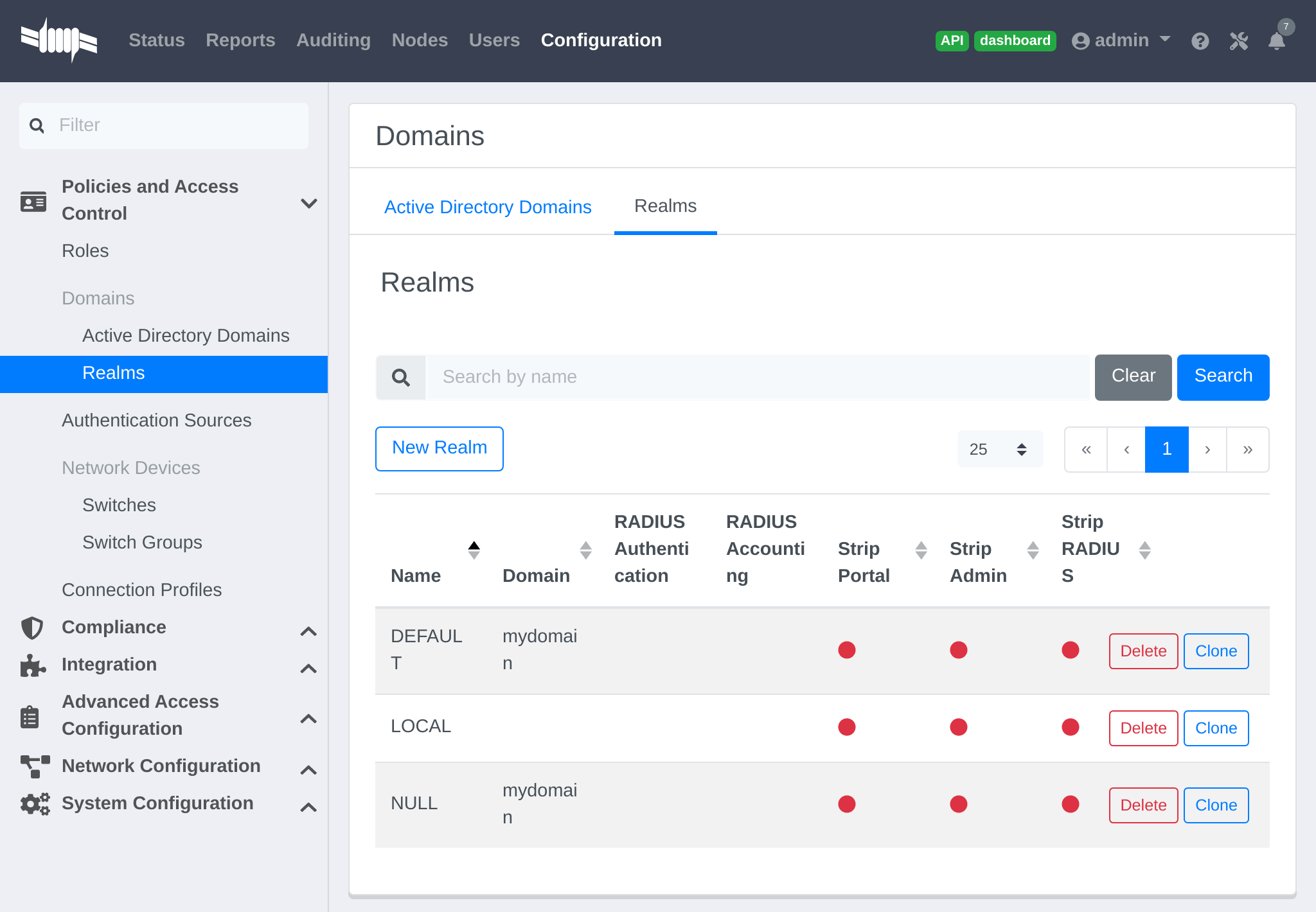
12.1.5. Windows subdomain joining limitations
PacketFence supports multiple domain authentications as well as authentications performed against domains and subdomains.
But be aware that according to Windows Domain Controller’s architecture and implementation, PacketFence cannot be joined on a subdomainif the subdomain shares the Domain Controller with the existing parent domain.
The only way to join PacketFence on a subdomain is to join it on a subdomain who has its own Domain Controller that belongs to a parent domain.
Check Microsoft’s Learn, FAQ and discussions about subdomain computer joining. https://learn.microsoft.com/en-us/answers/questions/342052/can-create-an-sub-domain-and-add-user-uder-the-cre
12.1.6. Authenticating using Windows Trusted Domains
PacketFence supports domain trust relations to be passed to the correct Domain Controller. However, there isn’t a way to configure the trusted domain settings from the Admin UI.
To authentication resources on a trusted domain, use the "--domain=" option in ntlm_auth_wrapper.
Manually modify PacketFence’s FreeRADIUS mschap module template file located at /usr/local/pf/conf/radiusd/mschap.conf
Locate the best mschap section that works for the situation and add a --domain=DOMAIN_TRUST_SETTINGS to the ntlm_auth_wrapper executable path.
After saving the changes, re-generate the FreeRADIUS configuration by restarting radius services and test if it works.
12.2. OAuth2 Authentication
The captive portal of PacketFence allows a guest/user to register using his Google, Facebook, LinkedIn, Windows Live, OpenID Connect or Github account.
For each providers, we maintain an allowed domain list to punch holes into the firewall so the user can hit the provider login page. This list is available in each OAuth2 authentication source.
Enable the passthrough option in the PacketFence configuration (fencing.passthrough in pf.conf).
12.2.1. Google
To use Google as a OAuth2 provider, get an API key to access their services.
Sign up here : https://code.google.com/apis/console.
In the Google APIs Console, go into Credentials → Create Credentials → OAuth
client ID → Web Application, then enter a name and use this URI for the
Authorized redirect URIs field :
https://YOUR_PORTAL_HOSTNAME/oauth2/callback. Of course, replace the hostname
with the values from general.hostname and general.domain.
Save to get the Client ID and Client secret.
Keep the default configuration, modify the App ID & App Secret (Given by Google on the developer platform) and Portal URL (https://YOUR_PORTAL_HOSTNAME/oauth2/callback).
Also, add the following Authorized domains : *.google.com, *.google.ca,
*.google.fr, *.gstatic.com,googleapis.com,accounts.youtube.com (Ensure to
have the google domain from the appropriate country like Canada ⇒ *.google.ca,
France ⇒ *.google.fr, etc…)
Once the client id, and API key are available, configure the OAuth2 provider. This can be done by adding a Google OAuth2 authentication source from Configuration → Policies and Access Control → Authentication Sources. Remember to add the Authentication Rules with at least two Actions (example: Role and Access duration).
Moreover, don’t forget to add Google as a Source from the connection profile definition, available from Configuration → Policies and Access Control → Connection Profiles.
12.2.2. Facebook
To use Facebook as an authentication source, an API code and a secret key
are also needed.
To get one, go here: https://developers.facebook.com/apps. When creating
the App, specify the following as the Website URL:
https://YOUR_PORTAL_HOSTNAME/oauth2/callback
Of course, replace the hostname with the values from general.hostname and
general.domain.
To find the secret, go in the newly created app, and click on Settings → Basic.
While in Settings → Basic, add YOUR_PORTAL_HOSTNAME in the App Domains field. Next, add the product Facebook Login. Click on Set up, and choose Web platform. Go through the 5 steps, then on the left side of the screen, go in Settings under Facebook Login. For Valid OAuth Redirect URIs, enter https://YOUR_PORTAL_HOSTNAME/oauth2/callback and then save changes.
Also, add the following Authorized domains : *.facebook.com, *.fbcdn.net,
*.akamaihd.net, *.akamaiedge.net, *.edgekey.net, *.akamai.net (May change)
Once the information is available, configure the OAuth2 provider. This can be done by adding a Facebook OAuth2 authentication source from Configuration → Policies and Access Control → Authentication Sources. Remember to add the Authentication Rules with at least two Actions (example: Role and Access duration).
Keep the default configuration, modify the App ID & App Secret (Given by Facebook on the developer platform) and Portal URL (https://YOUR_PORTAL_HOSTNAME/oauth2/callback).
Moreover, don’t forget to add Facebook as a Source from the connection profile definition, available from Configuration → Policies and Access Control → Connection Profiles.
12.2.3. Github
To use Github, an API code and a secret key are also needed. To get one, create an App here: https://github.com/settings/applications/new. When creating the App, specify the following as the Callback URL https://YOUR_PORTAL_HOSTNAME/oauth2/callback
Of course, replace the hostname with the values from general.hostname and
general.domain.
Once the information is available, configure the OAuth2 provider. This can be done by adding a GitHub OAuth2 authentication source from Configuration → Policies and Access Control → Authentication Sources. Remember to add the Authentication Rules with at least two Actions (example: Role and Access duration).
Moreover, don’t forget to add GitHub as a Source from the connection profile definition, available from Configuration → Policies and Access Control → Connection Profiles.
12.2.4. Kickbox
To use Kickbox, an API key is needed. To get one, first create an account on
https://kickbox.io, then navigate to
https://app.kickbox.com/settings/keys. Click on API Keys → Create Key.
Pick a name and choose Production mode and Single verification.
Once the API key is available, configure the OAuth2 provider. This can be done by adding a Kickbox authentication source from Configuration → Policies and Access Control → Authentication Sources. Remember to add the Authentication Rules with at least two Actions (example: Role and Access duration).
Moreover, don’t forget to add Kickbox as a Source from the connection profile definition, available from Configuration → Policies and Access Control → Connection Profiles.
12.2.5. LinkedIn
To use LinkedIn, an API code and a secret key are also needed. To get one, create an App here: https://developer.linkedin.com/. When creating the App, specify the following as the Callback URL https://YOUR_PORTAL_HOSTNAME/oauth2/callback
Get more details about how to configure the LinkedIn application inside Microsoft documentation.
Of course, replace the hostname with the values from general.hostname and
general.domain.
Once the information is available, configure the OAuth2 provider. This can be done by adding a LinkedIn OAuth2 authentication source from Configuration → Policies and Access Control → Authentication Sources. Remember to add the Authentication Rules with at least two Actions (example: Role and Access duration).
Moreover, don’t forget to add LinkedIn as a Source from the connection profile definition, available from Configuration → Policies and Access Control → Connection Profiles.
12.2.6. OpenID Connect
Using OpenID Connect is a bit different than other OAuth2 sources. The reason behind that is because setting up a custom OpenID Connect source or depending on a provider for it. Configuration like token path, authorize path or API URL are specific to the setup. For more information on how to create one’s own or get a host please visit: https://openid.net/connect/.
When creating the App, specify the following as the Callback URL, https://YOUR_PORTAL_HOSTNAME/oauth2/callback.
Of course, replace the hostname with the values from general.hostname and
general.domain.
OpenID connect have different ways to be configured, create a client ID and a client secret to work with PacketFence.
Once the information is available, configure the OAuth2 provider. This can be done by adding an OpenID OAuth2 authentication source from Configuration → Policies and Access Control → Authentication Sources. Remember to add the Authentication Rules with at least two Actions (example: Role and Access duration).
Moreover, don’t forget to add OpenID as a Source from the connection profile definition, available from Configuration → Policies and Access Control → Connection Profiles.
12.2.7. Twilio
To use Twilio, first create an account on https://www.twilio.com. From the
console (dashboard) https://www.twilio.com/console create a 3rd Party
Integration. Note the Account SID and Auth Token for later use. From the
Phone Manager https://www.twilio.com/console/phone-numbers/incoming click the
+ button to Buy a number with SMS capability - no payment is needed to
start using this phone number right away.
Once the information is available, configure the OAuth2 provider. This can be
done by adding a Twilio OAuth2 authentication source from Configuration →
Policies and Access Control → Authentication Sources. Enter the Account
SID, Auth Token and Phone Number (From) from above.
Remember to add the Authentication Rules with at least two Actions (example:
Role and Access duration).
Moreover, don’t forget to add Twilio as a Source from the connection profile definition, available from Configuration → Policies and Access Control → Connection Profiles.
12.2.8. Windows Live
To use Windows live, an API code and a secret key are also needed. To get
one, create an App here:
.https://portal.azure.com/#blade/Microsoft_AAD_RegisteredApps/ApplicationsListBlade
When creating the App, specify the following as the Callback URL
https://YOUR_PORTAL_HOSTNAME/oauth2/callback replacing the hostname with the
values from general.hostname and general.domain.
Once the information is available, configure the OAuth2 provider. This can be done by adding a WindowsLive OAuth2 authentication source from Configuration → Policies and Access Control → Authentication Sources. Remember to add the Authentication Rules with at least two Actions (example: Role and Access duration).
The App ID in PacketFence will be Application (client) ID in the Azure
portal.
The App secret must be a client secret created in the Certificates &
secrets section of the app on Azure AD. Note that Azure AD secrets do expire
so set a reminder to update the secret before it expires.
Moreover, don’t forget to add WindowsLive as a Source from the connection profile definition, available from Configuration → Policies and Access Control → Connection Profiles.
12.3. Eduroam
Eduroam (education roaming) is the secure, world-wide roaming access service developed for the international research and education community.
Eduroam allows students, researchers and staff from participating institutions to obtain Internet connectivity across campus and when visiting other participating institutions by simply opening their laptop.
https://www.eduroam.org/
PacketFence supports Eduroam and allows participating institutions to authenticate both locally visiting users from other institutions as well as allowing other institutions to authenticate local users.
Understanding of the Eduroam authentication workflow.
12.3.1. Local authentication
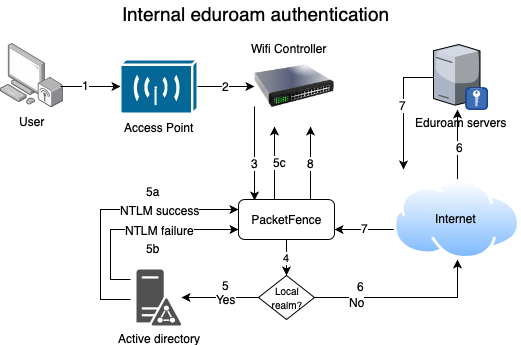
-
The device connects on the Eduroam SSID.
-
The access point forwards the authentication request to the wireless controller.
-
The controller sends the RADIUS authentication to PacketFence on port 11812.
-
PacketFence checks if it’s a local REALM.
-
If it’s local REALM, PacketFence does a NTLM request to the Active Directory (AD) domain controller to verify the identity. [loweralpha]
-
The AD validated the credentials.
-
The AD did not validate the credentials. PacketFence sends a RADIUS Reject.
-
After a successful NTLM authentication, PacketFence returns a Radius Access Accept to the wireless controller to apply the production VLAN for that MAC address.
-
-
If it’s a not local REALM, PacketFence proxies the radius request to the Eduroam servers.
-
The Eduroam servers validate the identity.
-
PacketFence returns a Radius Access Accept to the wireless controller to apply the production VLAN for that MAC address.
12.3.2. Configure the Eduroam source
Open the admin interface and go to Configuration → Policies and Access Control → Authentication Sources.
First, create RADIUS sources for each Eduroam servers you want to define.
To do that click New internal source and choose RADIUS.
Fill the Name, Description, Host, Port, Secret and disable Monitor. (The information to configure that source could be found on the Eduroam platform)
Next click on Exclusive Sources and click on New exclusive source then Eduroam.
Associate the Radius sources you previously configured in Eduroam RADIUS AUTH section, define the radius listening port and keep the type to Keyed Balance.
In order to handle correctly external and internal students with the Eduroam source, you will need to:
-
define realms used by the internal students in
Local Realmsfield - create a catchall rule which will assign a role (for example: eduroam) to external students
- create two different connection profiles (see next sections)
12.3.3. Create the connection profile to authenticate external students
Go to Configuration → Policies and Access Control → Connection Profiles → New Connection Profile.
Create a connection profile named External Eduroam authentication Check Automatically register devices then create a Realm filter eduroam. Make sure to add the previously created Eduroam source to match on the external users.
12.3.4. Create the connection profile to authenticate internal students
Go to Configuration → Policies and Access Control → Connection Profiles → New Connection Profile.
Create a connection profile named Local Eduroam authentication Check Automatically register devices then create a SSID filter Eduroam. Make sure to add the AD source to match on the local users.
External Eduroam authentication connection profile. Otherwise, it will also match request for external students and this is not what we want.12.3.5. Inbound authentication (TLRS to PF)
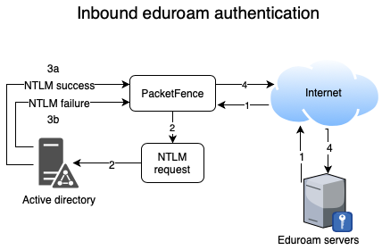
-
Eduroam sends the RADIUS authentication to a public IP address (NAT/PAT) bound to PacketFence on the management IP address (Management VIP for a cluster) on port 1812.
-
PacketFence forwards the NTLM request to the Active Directory.
-
NTLM response [loweralpha]
-
Successful user identify authentication on the AD
-
NTLM request fails because of a bad identity
-
-
PacketFence replies to the Eduroam servers either a RADIUS Access Accept for a sucessful authentication or a RADIUS access reject for an unsuccessful authentication. PacketFence sets the REALM to Eduroam for all successful authentications.
First, you need to refer to the previous step Configure the Eduroam source.
For this use case, there is no need to create a connection profile in PacketFence. FreeRADIUS will only perform a NTLM Auth and won’t send RADIUS request to PacketFence API.
12.4. SAML Authentication
12.4.1. Common SAML configuration
PacketFence supports SAML authentication in the captive portal in combination with another internal source to define the level of authorization of the user.
First, transfer the Identity Provider metadata on the PacketFence server. In this example, it will be under the path /usr/local/pf/conf/idp-metadata.xml.
Then, transfer the certificate and CA certificate of the Identity provider on the server. In this example, they will be under the paths /usr/local/pf/conf/ssl/idp.crt and /usr/local/pf/conf/ssl/idp-ca.crt. If it is a self-signed certificate, then you will be able to use it as the CA in the PacketFence configuration. Make sure -----BEGIN CERTIFICATE----- and -----END CERTIFICATE---- headers are present in these certificate files.
Then, to configure SAML in PacketFence, go in Configuration → Policies and Access Control → Sources and then create a new Internal source of the type SAML and configure it.
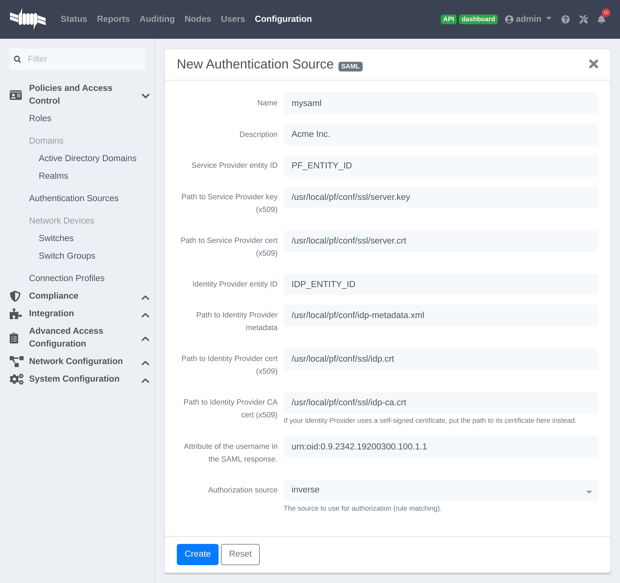
Where :
- Service Provider entity ID is the identifier of the Service Provider (PacketFence). Make sure this matches the Identity Provider configuration.
-
Path to Service Provider key is the path to the key that will be used by PacketFence to sign its messages to the Identity Provider. A default one is provided under the path :
/usr/local/pf/conf/ssl/server.key -
Path to Service Provider cert is the path to the certificate associated to the key above. A self-signed one is provided under the path :
/usr/local/pf/conf/ssl/server.crt -
Path to Identity Provider metadata is the path to the metadata file you transferred above (should be in
/usr/local/pf/conf/idp-metadata.xml) -
Path to Identity Provider cert is the path to the certificate of the identity provider you transferred on the server above (should be in
/usr/local/pf/conf/ssl/idp.crt). -
Path to Identity Provider CA cert is the path to the CA certificate of the identity provider you transferred on the server above (should be in
/usr/local/pf/conf/ssl/idp-ca.crt). If the certificate above is self-signed, put the same path as above in this field. - Attribute of the username in the SAML response is the attribute that contains the username in the SAML assertion returned by the Identity Provider. The default should fit at least SimpleSAMLphp.
-
Authorization source is the source that will be used to match the username against the rules defined in it. This allows to set the role and access duration of the user. The
Authenticationsection of this document contains explanations on how to configure an LDAP source which can then be used here.
Once this is done, save the source and you will be able to download the Service Provider metadata for PacketFence using the link Download Service Provider metadata on the page.
Configure the identity provider according to the generated metadata to complete the Trust between PacketFence and the Identity Provider.
In the case of SimpleSAMLPHP, the following configuration was used in metadata/saml20-sp-remote.php :
$metadata['PF_ENTITY_ID'] = array(`AssertionConsumerService` => `http://PORTAL_HOSTNAME/saml/assertion',`SingleLogoutService` => `http://PORTAL_HOSTNAME/saml/logoff',);
12.4.2. Entra ID SAML configuration
Microsoft Entra admin center
You need to make some configuration on the Microsoft Entra admin center in order to create the IDP.
First create a new Entreprise application:
Create an application:
Define a name and create:
Once the application has been created click on Single sign-on
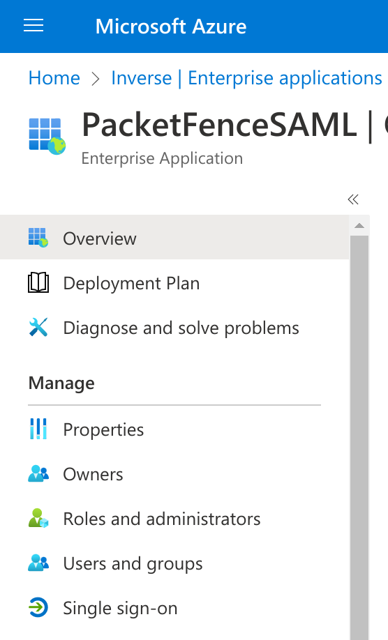
Click on SAML:
Then fill the information required in the section 1 (Note that the Identifier will need to match with what you will define in PacketFence):
On this page you have to download the Certificate (base64) and the Federation Metadata XML and copy the Azure AD Identifier.
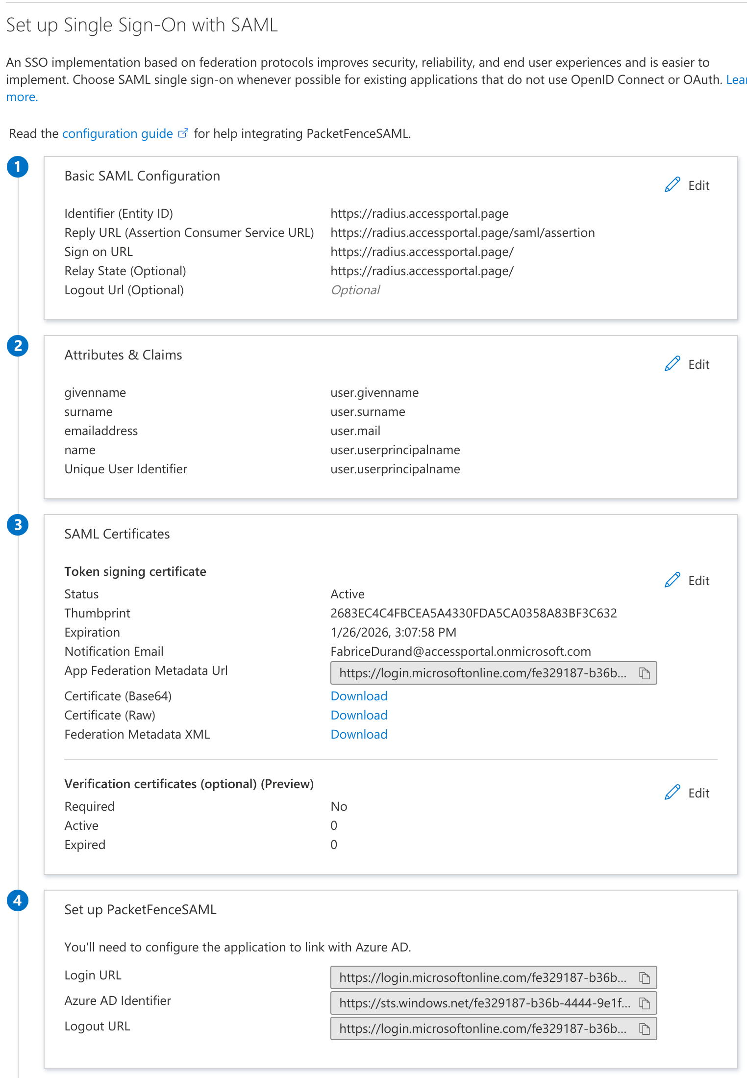
Last thing to do is to define which users can use this application, to do that go in "Users and Groups" section do add users or groups.
Azure SAML Source
On the PacketFence side, create a new Authentication Source SAML:
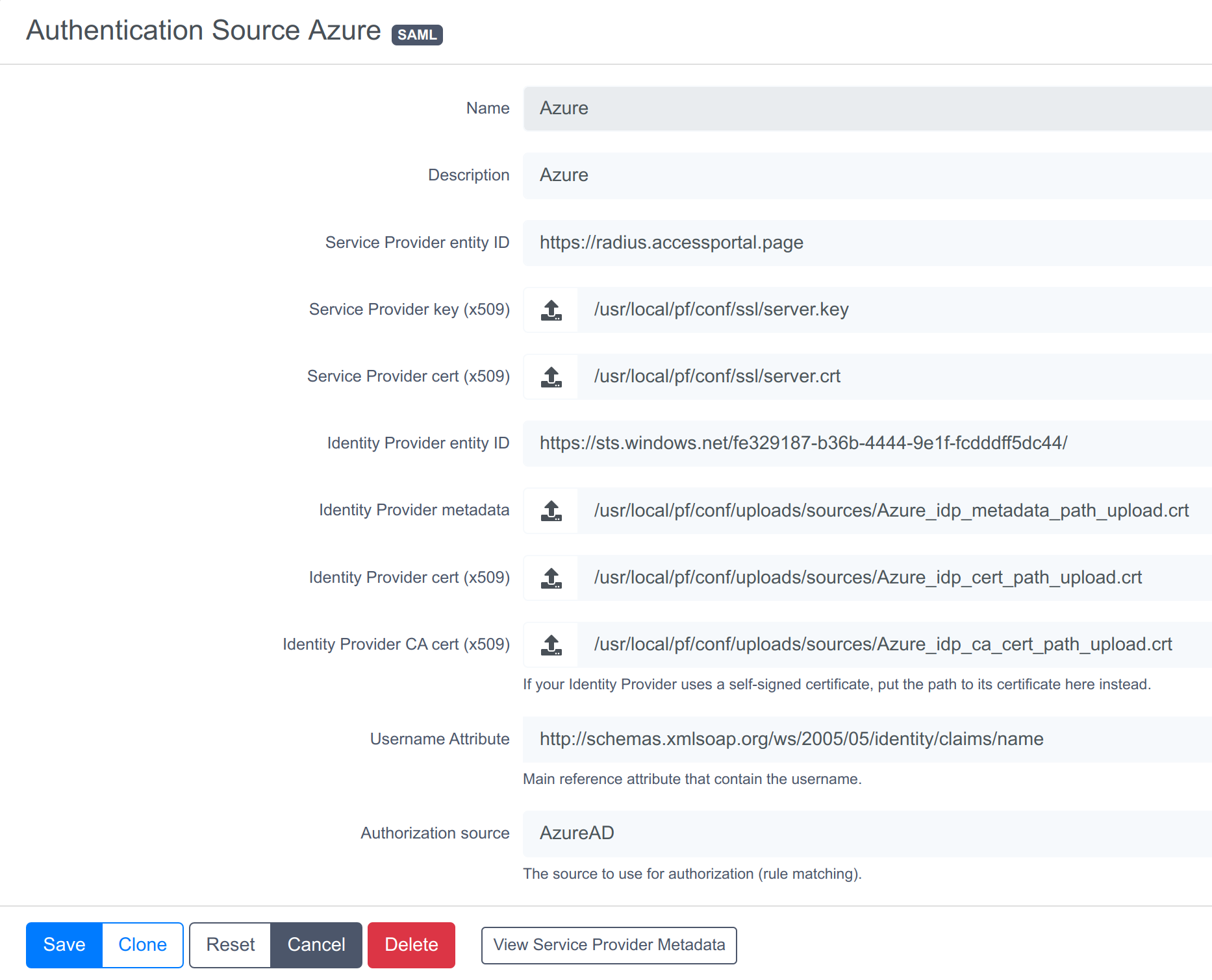
Where :
- Service Provider entity ID is the identifier of the Service Provider (PacketFence). In this example it’s "https://radius.accessportal.page".
-
Path to Service Provider key is the path to the key that will be used by PacketFence to sign its messages to the Identity Provider. A default one is provided under the path :
/usr/local/pf/conf/ssl/server.key -
Path to Service Provider cert is the path to the certificate associated to the key above. A self-signed one is provided under the path :
/usr/local/pf/conf/ssl/server.crt - Path to Identity Provider metadata Upload the XML file you previously downloaded from Azure.
- Path to Identity Provider cert Upload the certificate you previously downloaded from Azure.
- Path to Identity Provider CA cert Upload the certificate you previously downloaded from Azure (the same as the section above).
- Attribute of the username in the SAML response is the attribute that contains the username in the SAML assertion returned by the Identity Provider. The one that can be used with Azure is this one http://schemas.xmlsoap.org/ws/2005/05/identity/claims/name who return the "Unique User Identifier" (Edit the section 2 of the Azure SAML configuration detail to see which attribute can be used).
-
Authorization source is the source that will be used to match the username against the rules defined in it. This allows to set the role and access duration of the user or also the access level of the admin interface (if you have configured the "Advanced Access Control For Admin Login"). The
Authenticationsection of this document contains explanations on how to configure an Azure source which can then be used here.
12.4.3. Passthroughs
For users to access the Identity Provider login page, activate passthroughs and add the Identity Provider domain to the allowed passthroughs.
To do so, go in Configuration → Network Configuration → Networks → Fencing, then check Passthroughs and add the Identity Provider domain name to the Passthroughs list.
Next, restart pfdns services to apply the new passthroughs.
12.5. Billing Engine
PacketFence integrates the ability to use a payment gateway to bill users to gain access to the network. When configured, the user who wants to access the network / Internet is prompted by a page asking for it’s personal information as well as it’s credit card information.
PacketFence currently supports two payment gateways: Authorize.net, Paypal and Stripe.
To activate the billing, configure the following components :
- Billing source(s)
- Billing tier(s)
12.5.1. Configuring a billing source
First select a billing provider and follow the instructions below.
Paypal
If having a business account and not wanting to configure a test environment, skip the next section.
Sandbox account
To configure a sandbox paypal account for use in PacketFence, head to https://developer.paypal.com/ and either sign up or login into an existing account.
Then in the Sandbox menu, click Accounts
Create an account that has the type Personal and one that has the type Business.
Afterwards, go back into accounts, and expand the business account, then click Profile
Now, click the Change password link and change the password and note it.
Do the same thing with the personal account you created
Configuring the merchant account
Login into the Paypal business account that you created at https://www.sandbox.paypal.com/ if you are using a sandbox account or on https://www.paypal.com/ if you are using a real account.
Next, go to Account_Settings on the top right below the user account.
Next, in the Account Settings, select Website Payment → Website preferences
Configure the settings so they match the screenshot below.
Turn on Auto Return, set the return URL to https://YOUR_PORTAL_HOSTNAME/billing/paypal/verify.
Enable Payment data transfert and the Identity Token should appear, note it as it will be required in the PacketFence configuration.
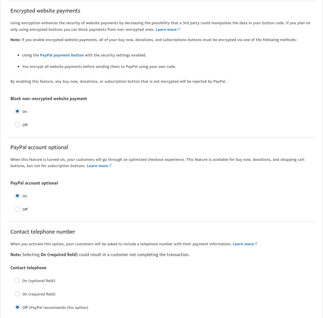
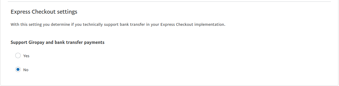
Next go back in Account_Settings on the top right below the user account, select Website Payment → Encrypted payment settings
Now on this page submit the certificate used by PacketFence to Paypal (/usr/local/pf/conf/ssl/server.crt by default).
Once submitted, note it’s associated Cert ID as it will need to be configured in PacketFence.
Still on that page, click the Download link to download the Paypal public certificate and put it on the PacketFence server under path : /usr/local/pf/conf/ssl/paypal.pem
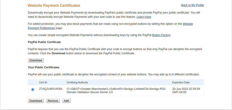
Configuring PacketFence
Now, in the admin interface, go to Configuration → Policies and Access Control → Authentication Sources and create a new source of type Billing → Paypal.
Where :
- Identity token is the one you noted when on the 'Website Payment Preferences' page.
- Cert ID is the one you noted when on the 'Encrypted Payment Settings'.
- Payment type is whether the access is donation based (not mandatory to pay for it).
- Email address is the email address of the merchant paypal account.
-
Cert file is the path to the PacketFence certificate (
/usr/local/pf/conf/ssl/server.crtby default). -
Key file is the path to the PacketFence certificate (
/usr/local/pf/conf/ssl/server.keyby default). -
Paypal cert file is the path to the Paypal certificate (
/usr/local/pf/conf/ssl/paypal.pemin this example). - Currency is the currency that will be used in the transactions.
- Test mode should be activated if you are using a sandbox account.
Passthroughs section of this document for detailsStripe
Stripe account
First go on https://dashboard.stripe.com, create an account and login.
Next on the top right click Account then Account settings.
Navigate to the API keys tab and note the key and secret. The test key should be used when testing the configuration and the live key when putting the source in production.
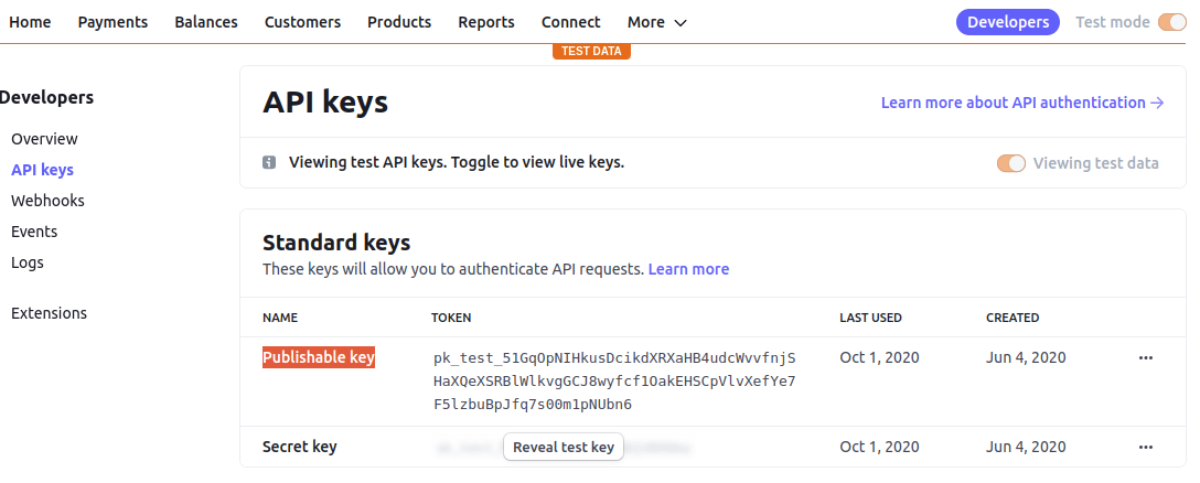
Configuring PacketFence
Now, in the admin interface, go to Configuration → Policies and Access Control → Authentication Sources and create a new source of type Billing → Stripe
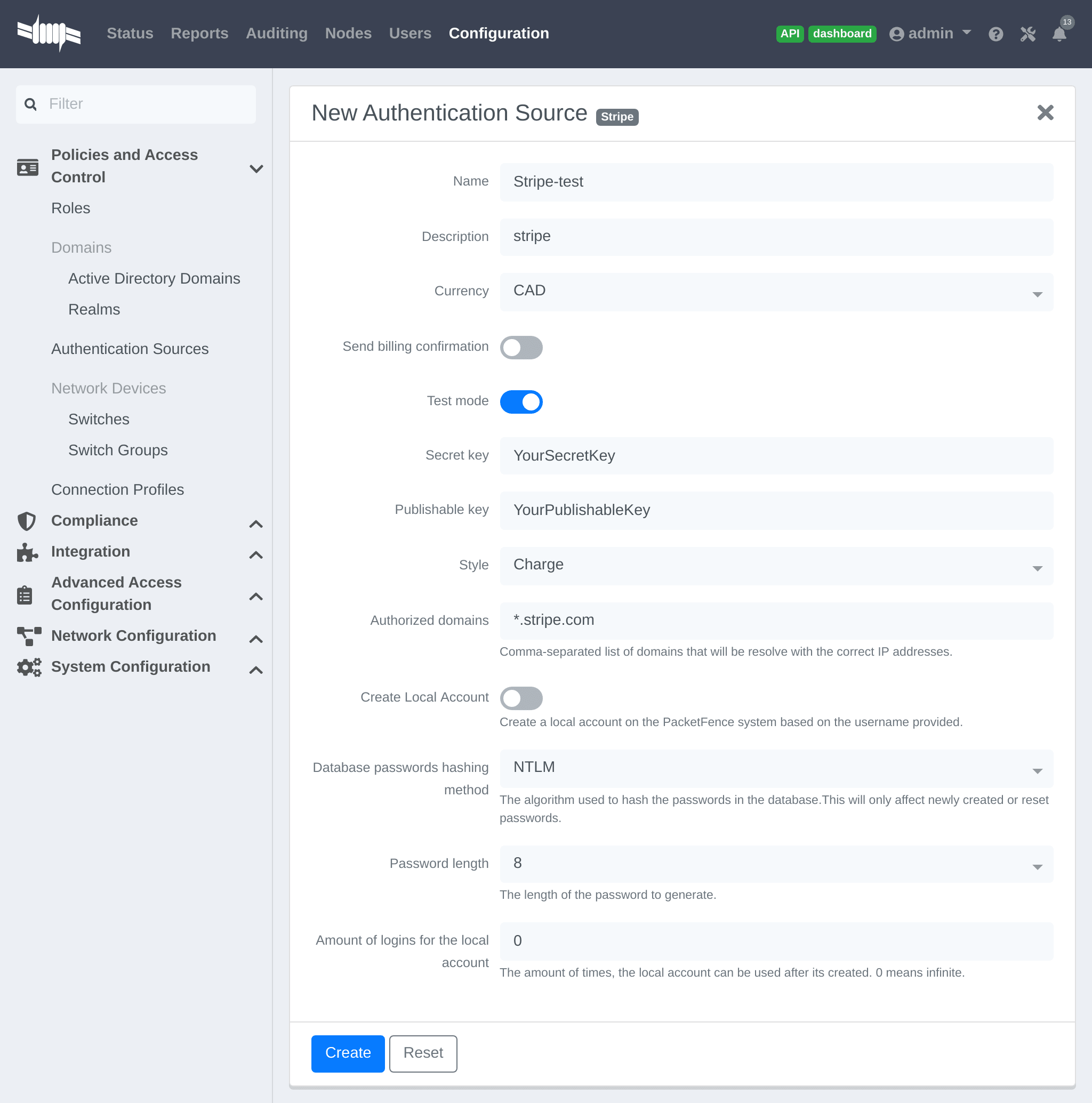
Where :
- Secret key is the secret key obtained from the Stripe account.
- Publishable key is the publishable key obtained from the Stripe account.
-
Style is whether you are doing a one-time charge or subscription based billing (recurring). See section
Subscription based registrationbelow for details on how to configure it. - Currency is the currency that will be used in the transactions.
- Test mode should be activated if you are using the test key and secret account.
Passthroughs section of this document for details.Stripe customer portal
PacketFence supports integrating with the Stripe customer portal and will handle subscription cancelations by default using webhooks. Additional hooks can be supported by extending lib/pf/billing/custom_hook.pm.
In order to enable the customer portal in Stripe, go in Settings → Product settings → Billing → Customer portal. Next, enable the options you want for the customer portal.
PacketFence supports the following options:
- Allow customers to view their invoice history
- Allow customers to update their billing information
- Allow customers to update their payment method
- Allow customers to cancel subscriptions
Optionally, once this is configured, ensure the captive portal is accessible publicly for Stripe to send it webhooks if subscription cancellations support is desired. Once its accessible publicly, configure a webhook to receive the event customer.subscription.deleted on https://PF_DOMAIN_NAME/hook/billing/STRIPE_SOURCE_ID. Replace STRIPE_SOURCE_ID by the identifier (name) of the Stripe source in the PacketFence configuration.
Next, in PacketFence, go in the Stripe source (Configuration → Policies and Access Control → Authentication Sources) and enable the option Customer portal in the Stripe source.
Now when users visit the status page (https://PF_DOMAIN_NAME/status), they will have the option to manage their subscriptions and visit the Stripe customer portal.
12.5.2. Adding billing tiers
Once you have configured one or more billing source, you need to define billing tiers which will define the price and target authentication rules for the user.
In the admin interface, go to Configuration → Advanced Access Configuration → Billing tiers
Then click Add billing tier and configure it.
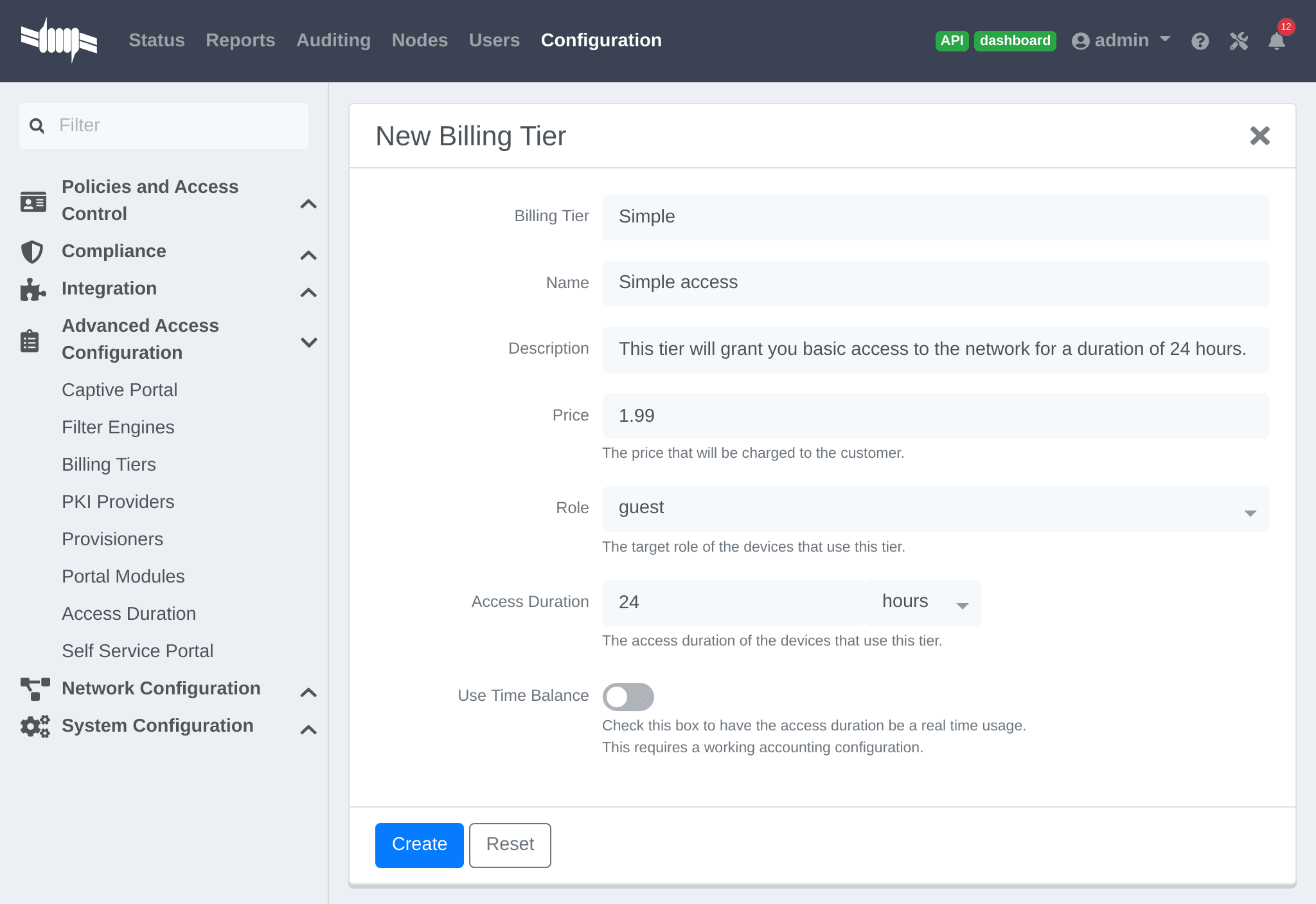
Where :
- Billing tier is the unique identifier of the billing tier.
- Name is the friendly name of the billing tier.
- Description is an extended description of the billing tier.
- Price is the amount that will be charged to the user.
- Access duration is the amount of time the user will be granted access to the network.
- Role is the target role the user should be in.
- Use time balance defines if the access duration should be computed on real-time access duration meaning if the user buys 24 hours of access he can use the network for 24 hours in different time blocks. This requires a valid RADIUS accounting configuration.
Connection profile.12.5.3. Subscription based registration
PacketFence supports subscription based billing using Stripe as a billing provider.
Stripe configuration
In the Stripe dashboard, go in Products → Add product.
Then create a new product.
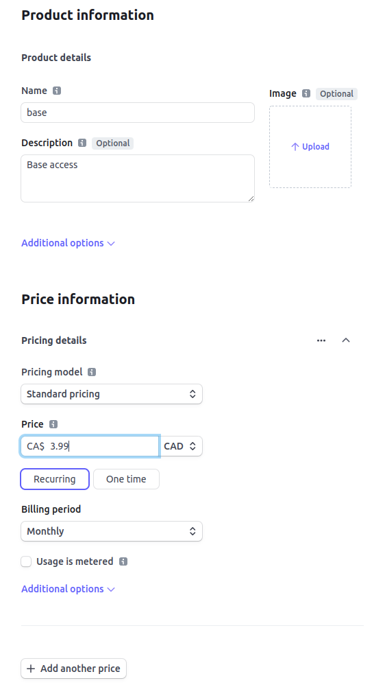
Where :
- Price is the price of the plan. It is important that this matches the price of the billing tier in PacketFence.
- Currency is the currency that will be used in the transactions. It is important that this matches the currency of the Stripe source in PacketFence.
- Billing period is the interval at which the customer should be billed. In the case of this example, it is monthly.
Save it and edit the product to see details information
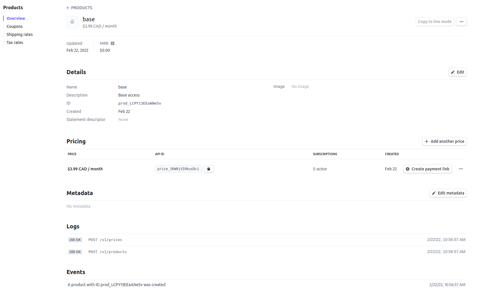
Where :
- API ID is the billing tier identifier. It is important that this matches the ID of the billing tier in PacketFence.
Now, following the same procedure, create the advance plan.
Billing tier
When using subscription based billing, it is advised to configure the billing tier so it has an almost infinite access duration (e.g. 20 years) as the billing provider will be contacting the PacketFence server when the subscription is canceled.
You should configure a billing tier for each subscription plan you want to have. This example will use the plan base and advance configured using the following parameters.
In this case price_1KW0jVIHkusDcikdVCGcvCii and price_1HFl6mIHkusDcikdZfIh5Bcj are the API ID copied from the 2 products.
[price_1KW0jVIHkusDcikdVCGcvCii]name=Base accessdescription=Click here if you are poorprice=3.99role=guestaccess_duration=10Yuse_time_balance=disabled[price_1HFl6mIHkusDcikdZfIh5Bcj]name=Advanced network accessdescription=Click here if you are poorprice=9.99role=advanced_guestaccess_duration=10Yuse_time_balance=disabled
Receiving updates from Stripe
As the subscription can be cancelled by a user, the PacketFence installation needs to be set up to receive updates from Stripe.
Updates are sent using HTTP requests on a public IP.
Ensure that the PacketFence server is available through a public IP on port 80 and that the PacketFence server hostname resolves on the public domain.
Then, in Stripe, configure a Webhook so Stripe informs PacketFence of any event that happens in this Stripe merchant account.
In order to do so go in Your Account → Developers → Webhooks and click Add an endpoint.
Where :
- URL is the URL to the PacketFence server. This should be http://YOUR_PORTAL_HOSTNAME/hook/billing/stripe
- Select events to listen to Select all the events
Now every time a user unsubscribes from a plan, PacketFence will be notified and will unregister that device from the network.
12.5.4. Extending access before it ends
PacketFence allows users to extend their access before it has ended. In order to do so, enable Allow access to registration portal when registered accessible via the Captive Portal tab of the Connection Profiles. Once this is activated, the users can reach https://PORTAL_IP/status and select Extend access in order to be able to access the billing section after they have registered.
12.6. External API Authentication
PacketFence also supports calling an external HTTP API as an authentication source. The external API needs to implement an authentication action and an authorization action.
12.6.1. Authentication
This should provide the information about whether or not the username/password combination is valid
These information are available through the POST fields of the request
The server should reply with two attributes in a JSON response
- result : should be 1 for success, 0 for failure
- message : should be the reason it succeeded or failed
Example JSON response :
{"result":1,"message":"Valid username and password"}
12.6.2. Authorization
This should provide the actions to apply on a user based on it’s attributes
The following attributes are available for the reply : access_duration, access_level, sponsor, unregdate, category.
Sample JSON response, note that not all attributes are necessary, only send back what you need.
{"access_duration":"1D","access_level":"ALL","sponsor":1,"unregdate":"2030-01-01","category":"default"}
/usr/local/pf/addons/example_external_auth for an example implementation compatible with PacketFence.12.6.3. PacketFence Configuration
In PacketFence, you need to configure an HTTP source in order to use an external API.
Here is a brief description of the fields :
- Host : First, the protocol, then the IP address or hostname of the API and lastly the port to connect to the API.
- API username and password : If the API implements HTTP basic authentication (RFC 2617) these can be added in these fields. Leaving any of those two fields empty will make PacketFence do the requests without any authentication.
- Authentication URL : URL relative to the host to call when doing the authentication of a user. Note that it is automatically prefixed by a slash.
- Authorization URL : URL relative to the host to call when doing the authorization of a user. Note that it is automatically prefixed by a slash.
12.7. External API Authentication
PacketFence also supports calling an external HTTP API as an authentication source. The external API needs to implement an authentication action and an authorization action.
12.7.1. Authentication
This should provide the information about whether or not the username/password combination is valid
These information are available through the POST fields of the request
The server should reply with two attributes in a JSON response
- result : should be 1 for success, 0 for failure
- message : should be the reason it succeeded or failed
Example JSON response :
{"result":1,"message":"Valid username and password"}
12.7.2. Authorization
This should provide the actions to apply on a user based on it’s attributes
The following attributes are available for the reply : access_duration, access_level, sponsor, unregdate, category.
Sample JSON response, note that not all attributes are necessary, only send back what you need.
{"access_duration":"1D","access_level":"ALL","sponsor":1,"unregdate":"2030-01-01","category":"default"}
/usr/local/pf/addons/example_external_auth for an example implementation compatible with PacketFence.12.7.3. PacketFence Configuration
In PacketFence, you need to configure an HTTP source in order to use an external API.
Here is a brief description of the fields :
- Host : First, the protocol, then the IP address or hostname of the API and lastly the port to connect to the API.
- API username and password : If the API implements HTTP basic authentication (RFC 2617) these can be added in these fields. Leaving any of those two fields empty will make PacketFence do the requests without any authentication.
- Authentication URL : URL relative to the host to call when doing the authentication of a user. Note that it is automatically prefixed by a slash.
- Authorization URL : URL relative to the host to call when doing the authorization of a user. Note that it is automatically prefixed by a slash.
12.8. Azure AD integration
PacketFence supports integrating with the Azure Active Directory for authenticating users on the captive portal, the admin interface and for 802.1X users using EAP-TTLS PAP. If your only goal is to authenticate users on the captive portal, using the OpenID implementation of Azure AD may be better suited. This section is aimed at providing username/password authentication through Azure AD.
12.8.1. Creating the PacketFence app
-
Open the 'Microsoft Entra ID' in your Azure portal
-
Go in 'Manage→App registrations→New registration'
-
Settings for the app
-
Name: PacketFence
-
Supported account types: Single tenant only - xyz (Single tenant)
-
Redirect URI must be left blank
-
Save the app
-
-
Note down the 'Application (client) ID' and 'Directory (tenant) ID' for later usage
-
In your application, go in 'Certificates & secrets' and select 'New client secret'
-
Description: PacketFence
-
Make sure you note down its expiry date so you can renew it before its expiration. Failure to do so will prevent authentication from working on PacketFence
-
Save the secret
-
-
Note down the 'Value' of your client secret for later usage
-
Still in your application, go to 'API permissions'
-
Click on 'Add a permission'
-
Go to the 'Microsoft APIs' tab
-
Select 'Microsoft Graph'
-
Select 'Application permissions'
-
Add the permission
Directory.Read.All -
Click on 'Grant admin consent'
-
-
Make sure
User.Readis already there as a delegated permission
-
-
12.8.2. Disabling MFA
Currently, PacketFence requires that multi-factor authentication be disabled for the PacketFence app. If you use Azure AD premium, you can create a rule to exclude this only for the PacketFence application. If you don’t use Azure AD premium, this must be disabled for all your users.
Disabling MFA using Azure AD premium
-
Open the "Microsoft Entra ID" in your Azure portal
-
Go in 'Manage→Properties'
-
Click 'Manage Security defaults'
-
Disable the toggle 'Enable Security defaults' and save
-
-
Next, go in 'Manage→Security→Conditional Access'
-
Click 'New policy' and enter the following settings:
-
Name: 2FA policy
-
Under 'Users and groups', select 'All users'
-
Under 'Cloud apps or actions', go in the 'Exclude' section and select the 'PacketFence' app you created earlier in the 'Select excluded cloud apps'
-
Under 'Grant', select 'Grant access' and check 'Require multi-factor authentication' and any other settings your organization requires.
-
At the bottom, make sure 'Enable policy' is set to 'On' and save your policy
-
-
Disabling MFA without Azure AD premium
-
Open the "Microsoft Entra ID" in your Azure portal
-
Under 'Manage', open 'Properties'
-
Click 'Manage Security defaults'
-
Disable the toggle 'Enable Security defaults' and save
-
12.8.3. Configuring PacketFence
-
In the admin interface, go to Configuration → Policies and Access Control → Authentication Sources, and create a new 'Azure Active Directory' internal source
-
Client ID: the 'Client ID' that was displayed while configuring the 'PacketFence' app inside Azure
-
Client Secret: the secret you created inside the 'PacketFence' app in Azure AD
-
Tenant ID: the 'Tenant ID' that was displayed while configuring the 'PacketFence' app inside Azure
-
User Groups URL: the API Url where to verify the groupmembership
-
Add any authentication or administration rules and then save the source
-
With this configuration, you can now use this source in your connection profiles to authenticate and authorize users on the captive portal and use it with EAP-TLS to authorize users (getting the role and access duration) as long as your EAP-TLS certificates use the distinguished name of the Azure AD users as their common name. Additionally, you can use this source for authenticating users in the admin interface and for VPN access.
Using Azure AD in 802.1X
You can perform 802.1X authentication of users using Azure AD but this will only work with supplicants configured to perform EAP-TTLS PAP which provides the RADIUS server with the plain-text password of the user. Support for this type of authentication is not as broad as EAP-PEAP MSCHAPv2 in the 802.1X supplicants but unfortunately Azure AD doesn’t support MSCHAP authentication. Refer to the documentation of your operating system on how to configure EAP-TTLS PAP. This section will only focus on enabling EAP-TTLS PAP for your Azure AD users in PacketFence.
-
In the admin interface, go to Configuration → Policies and Access Control → Realms, and create a new realm
-
Realm: enter the realm of your Azure AD users. Example, if the usernames have the following format
bob@inverseinc.onmicrosoft.com, then your realm isinverseinc.onmicrosoft.com -
Go in the 'Stripping' tab of the realm and select your Azure AD source under 'Azure AD Source for TTLS PAP'
-
Still in the 'Stripping' tab, disable (uncheck), the following settings:
-
Strip on the portal
-
Strip on the admin
-
Strip in RADIUS authorization
-
-
Save the realm
-
-
Restart radiusd using
/usr/local/pf/bin/pfcmd service radiusd restart -
All the users matching this realm will now authenticate against Azure AD. Make sure you also have a connection profile with auto-registration enabled and the Azure AD source in it so that your users are correclty authorized when connecting.
Using Azure AD EAP-TLS machine authentication
You can perform a EAP-TLS authentication and verify the machine group membership in order to provide a access to the network.
To do that first you will have to provide to the end device a certificate that contains the Device ID, to do this go in the Intune management interface and configure the template like this:
As you can see the CN (Common Name) will contain the Device Identifier, so when the device will connects on the secure SSID, the username will be equal to the device ID (like 8df07f7e-d98e-4579-aa97-bfcfaaa7fe38)
Now it just a matter to retrieve the group membership associated with the device ID, in order to do that you will need to change the "User Groups URL" parameter in the "Azure Active Directory" authentication source.
The URL will be
https://graph.microsoft.com/v1.0/devices(deviceId='%USERNAME')/memberOf (for
more information
https://learn.microsoft.com/en-us/graph/api/device-list-memberof?view=graph-rest-1.0&tabs=http)
In this example the API call will be `https://graph.microsoft.com/v1.0//devices(deviceId='8df07f7e-d98e-4579-aa97-bfcfaaa7fe38')/memberOf?$select=id,displayName and the reply will be:
{
   "value""⇒"[
      {
         "displayName""⇒""ZaymLed-Devices",
         "id""⇒""5c5f932c-08d4-46c3-bd93-11807f80ae35",
         "@odata.type""⇒""#microsoft.graph.group"
      },
      {
         "id""⇒""6ae04238-8e95-4f1b-8088-17c0d6cfbd98",
         "displayName""⇒""3D printer Laptop manager",
         "@odata.type""⇒""#microsoft.graph.group"
      },
      {
         "@odata.type""⇒""#microsoft.graph.group",
         "id""⇒""c2e304d6-f245-4ab2-8f60-58d78e57c526",
         "displayName""⇒""Windows 11 Feature Updates"
      },
      {
         "@odata.type""⇒""#microsoft.graph.group",
         "id""⇒""1bced11e-0cae-4689-8afa-060ec0b3341f",
         "displayName""⇒""ZaymLed - 3D software"
      },
   ],
   "@odata.context""⇒""https://graph.microsoft.com/v1.0/$metadata#directoryObjects(id,displayName)"
}
From the "Azure Active Directory" authentication source, create an authentication rule like this:"
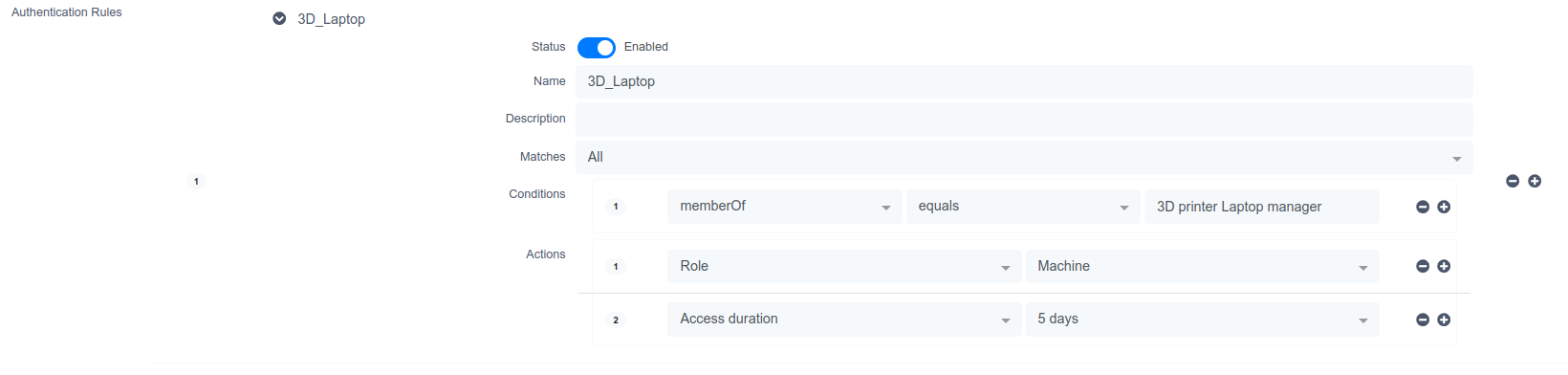
12.9. Google Workspace LDAP Integration
-
Go to https://admin.google.com/ and sign in as a Google Workspace domain administrator.
-
Go to Apps > LDAP > Add Client.
-
Provide an LDAP client name and an optional Description. Any descriptive values are acceptable. For example, the name could be ‘PacketFence’ and the description could be ‘PacketFence LDAP Client’. Click the Continue button.
-
Set Access Permission as needed. You must choose either ‘Entire domain (PacketFence)’ or ‘Selected organizational units’ for both ‘Verify user credentials’ and ‘Read user information’. Select ‘Add LDAP Client’
-
Download the generated certificate. This is required for PacketFence to communicate with the Google Secure LDAP service. Save the downloaded certificates for later use. After downloading, click the Continue to Client Details button.
-
Expand the Service Status section and turn the LDAP client ‘ON for everyone’. After selecting ‘Save’, click on the ‘Service Status’ bar again to collapse and return to the rest of the settings.
-
Expand the Authentication section and choose ‘Generate New Credentials’. Copy/note these credentials for later use. After selecting ‘Close’, click on the ‘Authentication’ bar again to collapse and return to the rest of the settings.
12.9.1. Configuring PacketFence
-
Under 'Configuration→Policies and Access Control→Authentication Sources', create a new 'Google Workspace LDAP' internal source
-
The following are the configuration values obtained during the LDAP client configuration earlier:
-
Bind DN: The access credentials username
-
Password: The access credentials password
-
Client Certificate: The .crt file text from the downloaded certificate bundle
-
Client Key: The .key file text from the downloaded certificate bundle
-
-
You will also need to these properties for the Authentication Source:
-
Host:
ldap.google.com/ Port:636/ Type:SSL -
SSL Verify Mode:
None -
Base DN: (this is the ldap path for your domain.. usually something like this:
dc=example,dc=comif your email is @example.com) You might have to addou=Users,as a prefix in some cases, so it would beou=Users,dc=example,dc=com -
Scope:
Subtree -
Username Attribute:
uid(unless you’ve heavily customized your Google Workspace directory) -
Email Attribute:
mail -
Associated Realms: You’ll need to match a previously created realm which matches your
example.comdomain. This will let the system strip the domain part when searching for the user and also let the system know which source to use for which specific realms (the @example.com part of the username) are used for each source.
-
-
For Authentication and Administration rules, you can match against google group membership (if you have configured google to allow group membership access - this is done when creating the LDAP client on the Google workspace configuration page on Google’s side, not on PacketFence). In that case, you will want to use the condition
memberOf, a match ofequalsand the value ofcn=mygroupname,ou=Groups,dc=example,dc=comif your group is called "mygroupname`. Keep in mind that nested group membership does not work via ldap for google workspace.
-
12.10. Advanced Access Control For Admin Login
PacketFence admin interface allows username/password login via any Internal authentication source (local database, LDAP, etc) by default.
For other admin interface authentication types (SAML, multi-factor auth, etc), leverage captive portal capabilities for administrator authentication.
12.10.1. Basic Configuration
In the admin interface, go to Configuration → System Configuration → Admin Login and enable 'SSO Status'. To enforce SSO policy for login (disable username/password), disable 'Allow username/password authentication'.
Configure 'SSO Base URL' if PacketFence captive portal uses different name than 'Hostname' and 'Domain' values in 'General Configuration'.
Configure connection profile for administrator authentication. In the admin interface, go to Configuration → Policies and Access Control → Connection Profiles and create new connection profile:
- Root Portal Module: 'Default admin SSO policy'
- Filter: URI with value '/admin-sso'
- Sources: The authentication sources that should be used for the login.
Restart api-frontend and httpd.portal. Admin interface login page shows new
'Single Sign On' option (text changeable in 'Admin Login' configuration).
Any portal authentication mechanism (SAML, Akamai MFA, TOTP, etc) can authenticate administrators. Refer to appropriate sections in this guide to configure features on administrator authentication connection profile.
12.10.2. Advanced Configuration
Adjust captive portal policy configuration for administrator authentication as needed. Portal modules provide flexibility and customization. Modify 'Default admin SSO policy' in Configuration → Advanced Access Configuration → Portal Modules or create custom policy for administrator authentication connection profile. See Portal Modules section for captive portal customization.
13. Advanced Portal Configuration
13.1. Portal Modules
PacketFence captive portal flow is highly customizable. Portal Modules define captive portal behavior.
Available Portal Modules:
-
Root: Container defining modules applied in chain to user. Device is released after completing all Root modules. -
Choice: Choice between multiple modules. Seedefault_registration_policyexample. -
Chained: Ordered modules for user completion. Example: Google+ registration then PayPal payment. -
Authentication: Multiple types available. Define modules to override required fields, source, template or other attributes.-
Billing: One or more billing sources. -
Choice: Multiple sources and modules with advanced filtering. See Authentication Choice module below. -
Login: Username/password for multiple internal sources (Active Directory, LDAP, etc.).
-
-
Other: Modules based on assigned source type, allowing source selection, AUP acceptance, and mandatory fields.-
Message: Display message to user. Example in Displaying a message to the user after registration. -
SelectRole: Override role during device registration. Admin users can choose device role during registration, bypassing authentication rules. -
URL: Redirect to local or external URL that may return to portal. Example in Calling an external website.
-
13.1.1. Examples
Creating a custom root module
In Configuration → Advanced Access Configuration → Portal Modules, create a
New Root Module that won’t affect default policy. Name it
my_first_root_module with description "My first root module", then click
Save.
In Configuration → Policies and Access Control → Connection Profiles, select
the connection profile (likely default) and set Root Portal Module to
my_first_root_module, then click Save.
Prompting for fields without authentication
To prompt fields to users without authentication, use the Null source with the Null Portal Module.
A pre-configured Null source is included. If it has not been modified or deleted it can be used for this example. Otherwise, in Configuration → Policies and Access Control → Sources, create a new Null source with a catchall rule that assigns a role and access duration.
In Configuration → Advanced Access Configuration → Portal Modules, click
"New Module" and select "Authentication → Authentication::Null". Set the
"Identifier" to prompt_fields and configure the Portal Module with the
desired "Mandatory fields" and uncheck "Require AUP" so users do not have to accept the AUP before submitting the form.
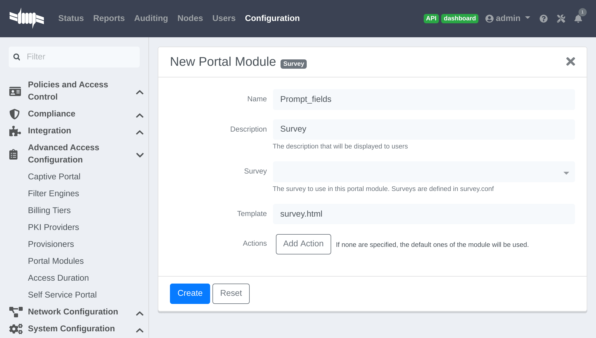
In my_first_root_module add the prompt_fields module (remove all previous
modules), then click Save. The portal will now prompt users for the fields defined in the module. Once submitted these fields are used to assign the role and access duration that is defined in the "Null source".
Prompting additional fields with authentication
To prompt additional fields to users during authentication, define a Module based on the source which specifies additional mandatory fields.
Additional mandatory fields can be added to the default pre-configured policies.
Example requiring users to enter a value for "first name", "last name" and "address" before registering:
In Configuration → Advanced Access Configuration → Portal Modules, choose
"Authentication::Choice → Guest Signup" (default_guest_policy). Add
firstname, lastname and address to "Mandatory fields", then click Save.
In my_first_root_module add the default_guest_policy module (removing any
previous modules). Any guest sources configured in connection profiles now
require users to enter the mandatory fields of the source (ex: phone + mobile provider) AND the mandatory fields defined in the default_guest_policy.
Chained authentication
Two or more modules may be chained together in order to make users accomplish all of the actions of each module in the desired order.
Example requiring users to login using any configured OAuth source (Github, Google+, …) and then validate their phone number with SMS registration:
Use the default_oauth_policy for OAuth login, and ensure an OAuth source is
configured and available in Connection Profiles.
Create a Portal Module that will contain the SMS registration definition.
In Configuration → Advanced Access Configuration → Portal Modules, click
"New Module" and select type "Authentication → SMS". Set the "Identifier"
to prompt_sms and configure the Portal Module with with sms Authentication
Source, and uncheck "Require AUP" since users will already have accepted the AUP earlier when registering with OAuth.
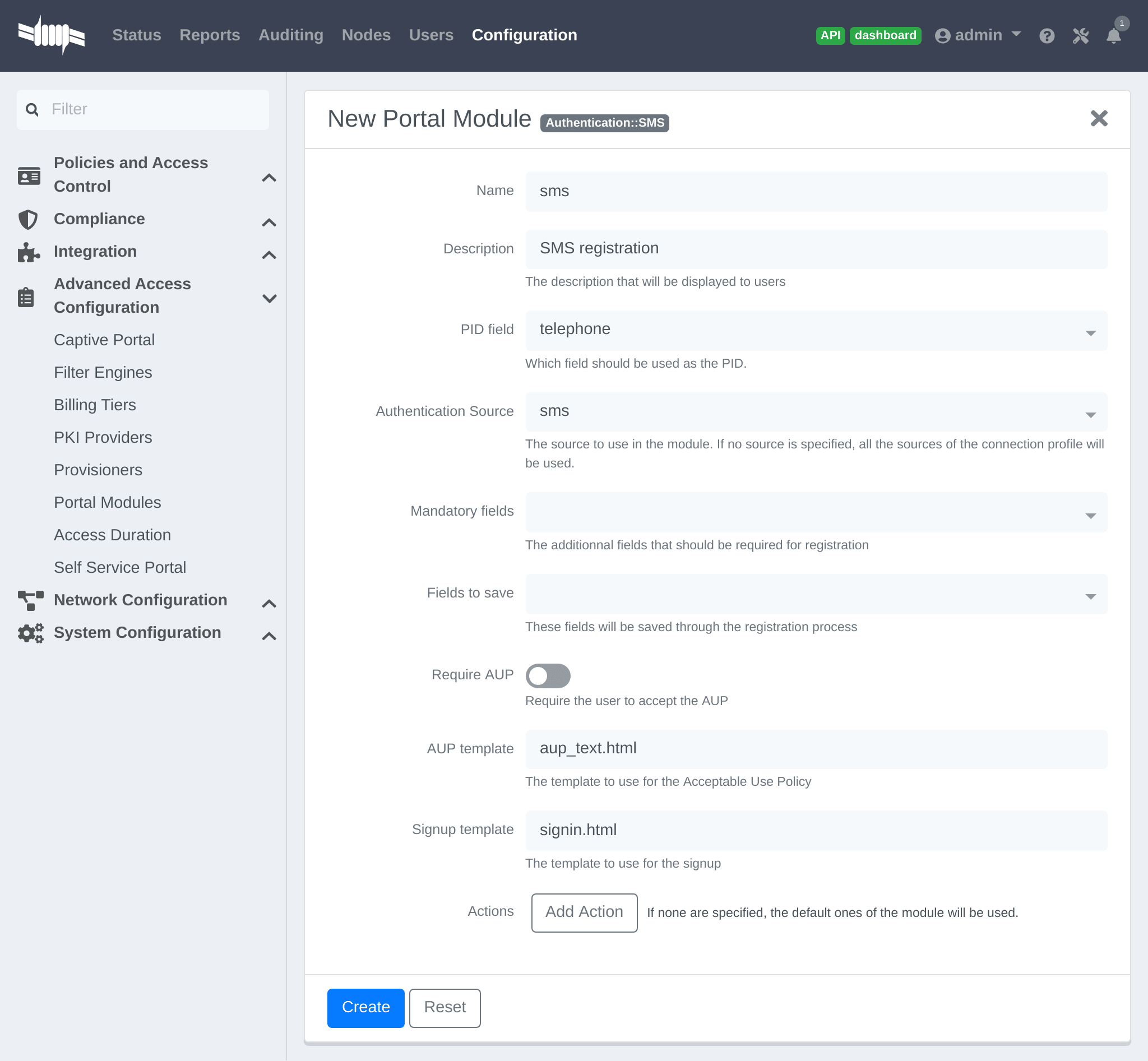
Add another "New Module" of type " Multiple → Chained", name it
chained_oauth_sms, provide a relevant description, add default_oauth_policy
and prompt_sms to the "Modules", then click Create.
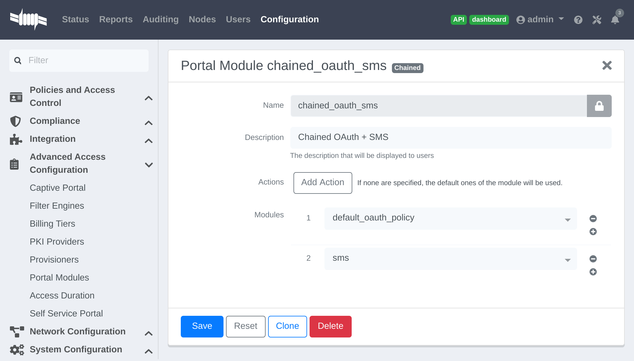
In my_first_root_module add the chained_oauth_sms module (removing any
previous modules), then click Save. The portal will now prompt users for authentication using an OAuth source and then with SMS.
telephone to the first module’s "Saved Fields" will persist through all subsequent modules in the chain, and subsequent modules will not prompt users again for a field that is already saved.Mixing login and Secure SSID on-boarding on the portal
Devices can access an open SSID with LDAP username/password, and then a Provisioner handles the remainder of the device on-boarding.
Configure the Provisioners for Secure SSID onboarding. Refer to the Apple and Android Wireless Provisioning section of this guide to configure the provisioners and add them to the Connection Profile.
Create a new provisioner with type Deny at the bottom of the list with the existing provisioners. This ensures the device is not allowed if no other provisioner is matched.
In the Connection Profile set the Sources to only the LDAP source, removing any other sources.
In Configuration → Advanced Access Configuration → Portal Modules, click
"New Module" and select type "Other → Provisioning". Set the "Identifier"
to secure_boarding, provide a relevant description, and uncheck "Skippable"
so users are forced to board the SSID if this option is chosen.
In Configuration → Advanced Access Configuration → Portal Modules, click
"New Module" and select type "Multiple → Choice" . Set the "Identifier"
to login_or_boarding, and provide a relevant description. Add
secure_boarding and default_login_policy to the "Modules", then click
Create.
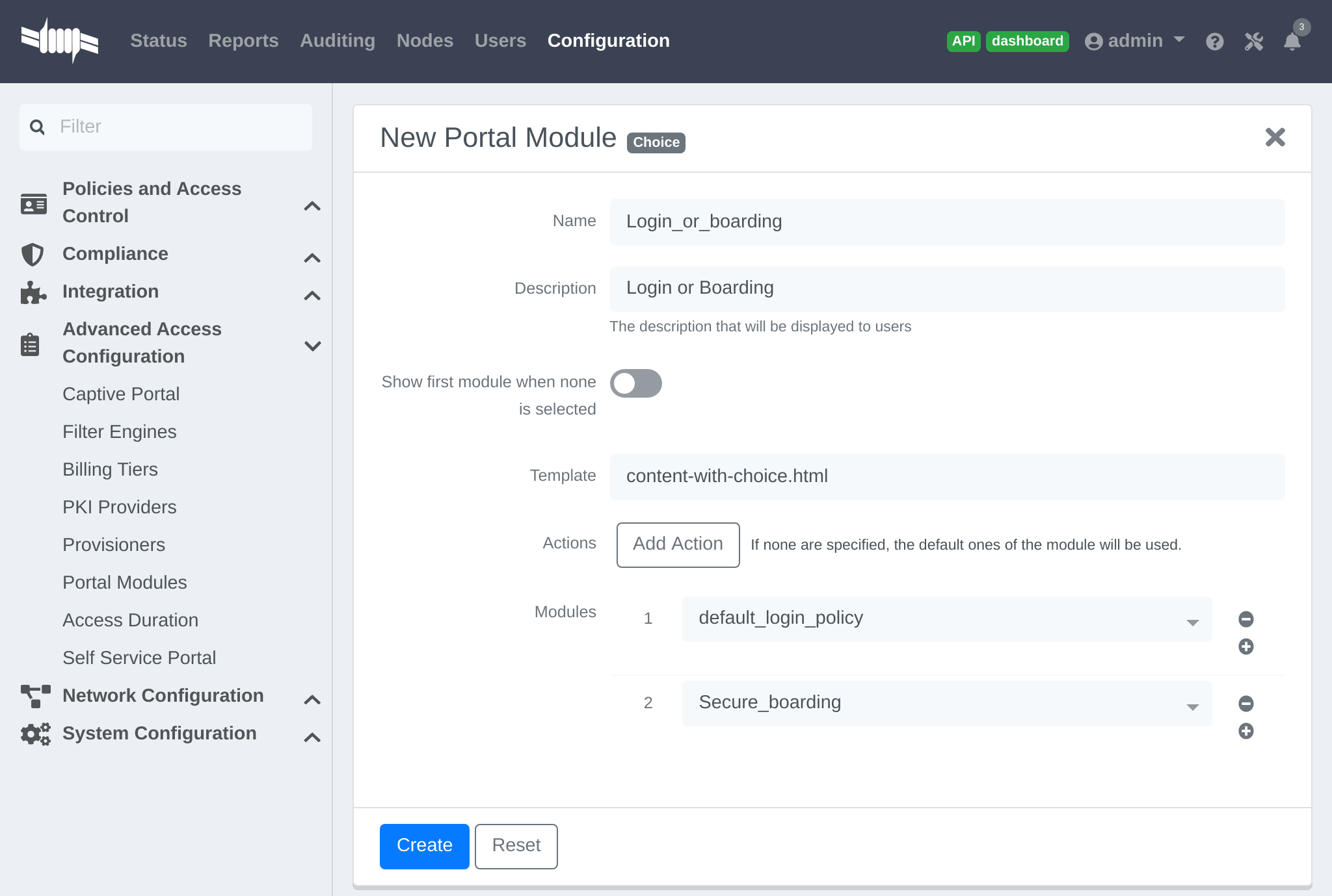
In my_first_root_module add the login_or_boarding module (removing any
previous modules), then click Save. The portal will now prompt users with a choice to either login to the network directly with the LDAP source, or use provisioning to configure the device for a Secure SSID.
Display a message to the user after registration
A custom message can be displayed to users using the Message Portal Module.
In Configuration → Advanced Access Configuration → Portal Modules, click
"New Module" and select type "Other → Message". Set the "Identifier" to
hello_world, provide a relevant description.
Add the following text in the "Message" field, then click Create:
Hello World !<a href="https://www.packetfence.com">Click here to access the PacketFencewebsite!</a>
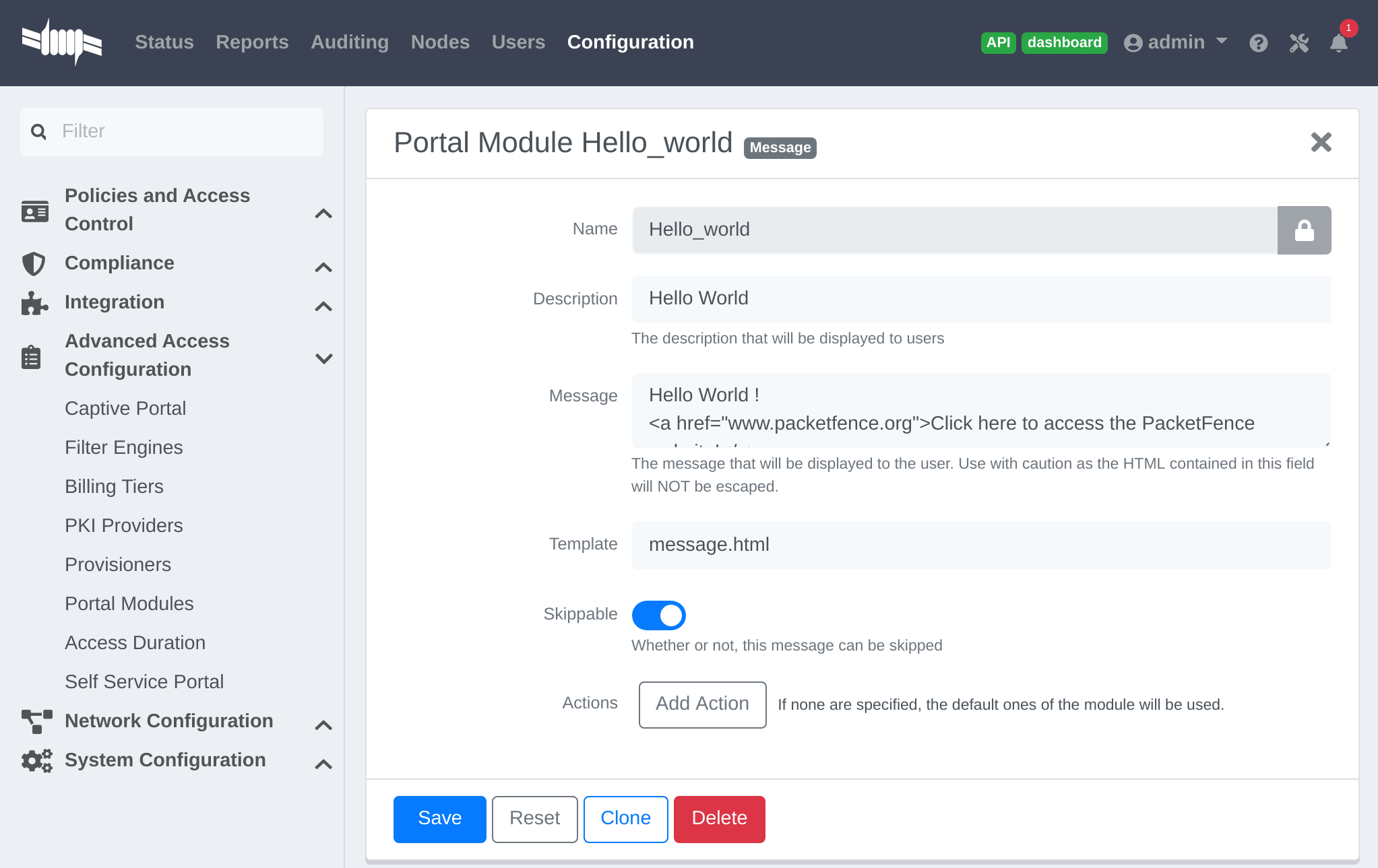
In my_first_root_module add the default_registration_policy and
hello_world modules (removing any previous modules), then click Save. The
portal will now prompt users for authentication using the Sources defined in the Connection Profile, and once registered the Hello World Message is displayed.
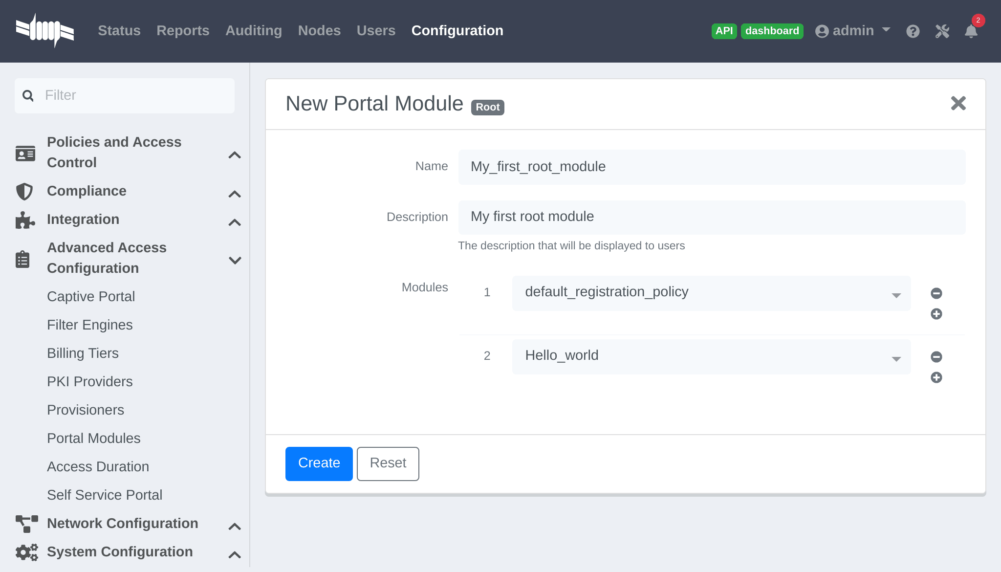
Redirect to an external website
Users can be redirected to either a local or external URL (if included in passthroughs) using the "URL" Portal Module. In order for the Portal flow to continue the Module must accept a callback, otherwise users are redirected without the possibility to continue with the registration process.
An example script redirecting users to an externally hosted PHP script that
provides a random token and performs a callback to the portal in order to
complete the registration process is located in
/usr/local/pf/addons/example_external_auth/token.php including a
README to help set it up.
Once the script is installed and working at the URL:
http://YOUR_PORTAL_HOSTNAME:10000/token.php, in Configuration → Advanced
Access Configuration → Portal Modules, click "New Module" and select type
"Other → URL". Set the "Identifier" to token_system, provide a relevant
description, and set the "URL" to
http://YOUR_PORTAL_HOSTNAME:10000/token.php.
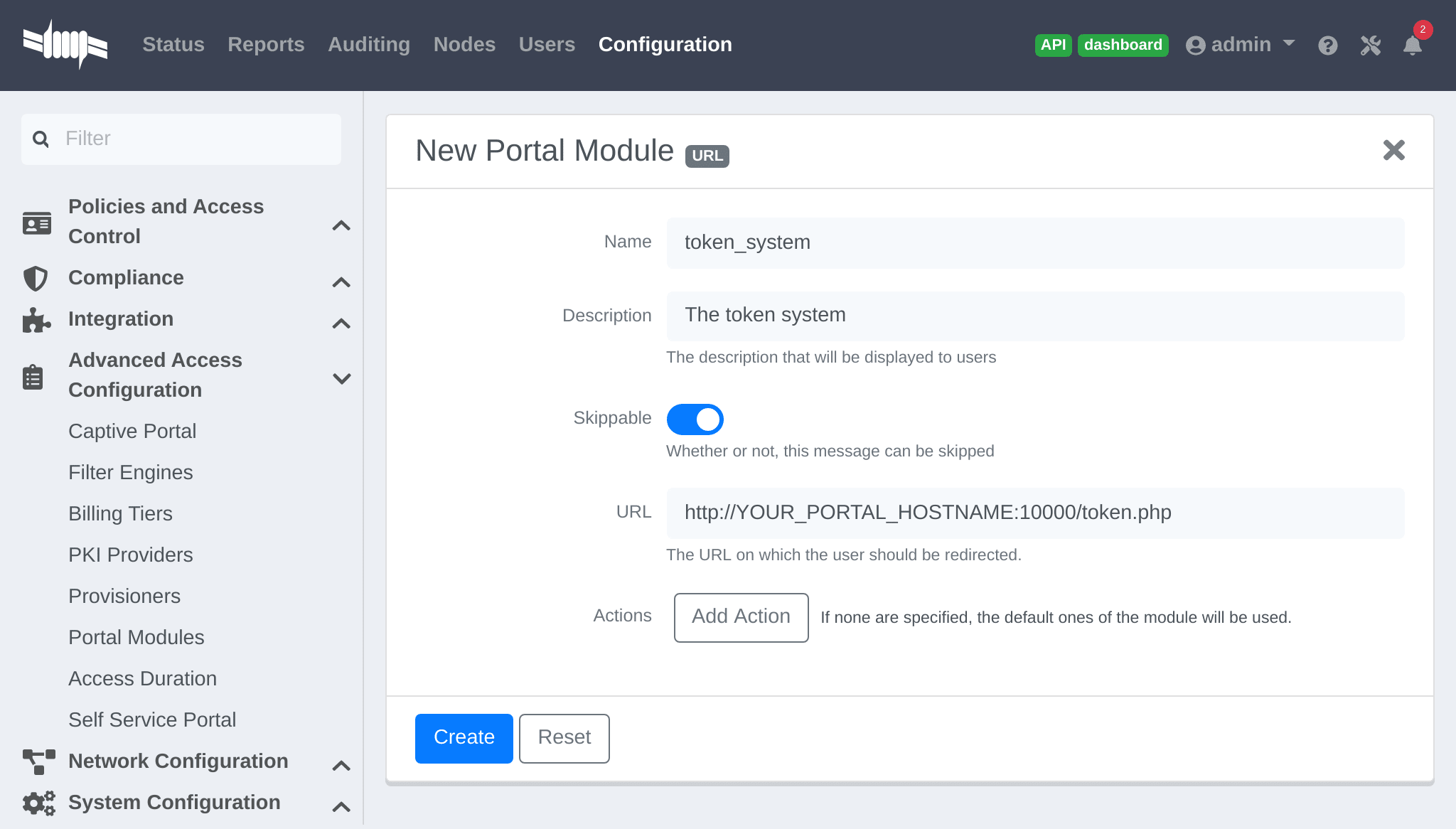
In my_first_root_module add the token_system module (removing any previous
modules), then click Save. The portal will now prompt users for authentication using the Sources defined in the Connection Profile, and then users are redirected to the token_system URL. From there, once users continue they are redirected back to the Portal in order to complete the registration process.
13.1.2. Authentication Choice module (Advanced)
Provides users a choice between multiple sources using advanced filtering rules, manual selection of the Sources and selection of the Portal Modules.
default_guest_policy and default_oauth_policy provide good
examples.All the defined "Sources" and "Modules" are available for use. Mandatory fields can be defined in the module, but they will only be shown if applicable to the Source.
Dynamically select a Source from the Connection Profile based on an object attribute (Object Class, Authentication Type, Authentication Class).
-
Source(s) by Class: Specify the perl class name of the available source(s).-
ex:
pf::Authentication::Source::SMSSourceselects all the SMS source(s). -
ex:
pf::Authentication::Source::BillingSourceselects all the billing sources (Paypal, Stripe, …).
-
ex:
-
Source(s) by Type: Filter sources with thetypeattribute of the Authentication object. -
Source(s) by Auth Class: Filter sources with theclassattribute of the Authentication object.
/usr/local/pf/lib/pf/Authentication/Source.13.1.3. SelectRole
Manually define specific roles when registering a device. This is useful for a technical crew to register new devices.
In Configuration → Advanced Access Configuration → Portal Modules, click "New Module" and select type "Other → Select Role". In "Admin Roles" chose the user role(s) that is required to use this module. In "Roles" choose the user role(s) that can then be assigned.
For example; technicians in the AD group technical support will have the role
technical support while registering. In "Admin Roles" add technical
support, then in "Roles" add default, voice and guest. Technicians that
have the technical support role will be prompted to assign either the
default, voice or guest role when registering a new device.
13.1.4. Actions on_failure and on_success
The on_failure and on_success "Actions" allow the creation of a more
complex workflow and permit the root portal module change based on the result of
authentication.
Consider that a root portal module is linked to an Authentication::Login
module and associated with a Connection Profile. In order to present a Guest
authentication if the login failed, configure a New Root Module called "Guest
portal policy" with the "Module" set to Authentication::SMS, and in the
previous "Authentication::Login" module add the "Action" on_failure ⇒
Guest portal policy.
13.2. Portal Surveys
Surveys can be presented on the Captive Portal where results are stored in a dedicated database.
13.2.1. Database Setup
To automatically create the database tables required by the Survey, the MySQL
pf user must be granted the CREATE and ALTER privileges. The MySQL root user
must be used to GRANT these privileges.
Access the MYSQL CLI as the root user:
mysql -uroot -p
From the MySQL CLI grant the privileges:
GRANT CREATE,ALTER ON pf.* TO 'pf'@'%';GRANT CREATE,ALTER ON pf.* TO 'pf'@'localhost';FLUSH PRIVILEGES;
root password was only provided during Configuration and not
stored on disk.13.2.2. Configuring the survey
Configure the survey in /usr/local/pf/conf/survey.conf. Here is an
example of a survey:
[survey1]description=Mustard Turkey Sandwich Brothers[survey1 field gender]label=What is your gender?type=Selectchoices=<<EOTM|MaleF|FemaleEOTrequired=yes[survey1 field firstname]label=What is your firstname?type=Textrequired=yes[survey1 field lastname]label=What is your lastname?type=Textrequired=yes[survey1 field sandwich_quality]label=On a scale of 1 to 5, how good was your sandwich today?type=Scaleminimum=1maximum=5required=yes[survey1 field preferred_sandwich]label=What is your preferred sandwich?type=Selectchoices= <<EOTClassic|ClassicExtra Turkey|Sandwich with extra turkeyExtra Mustard|Sandwich with extra mustardEOTrequired=yes[survey1 field comments]label=Enter any additional comments heretype=TextArearequired=no[survey1 data ssid]query=node.last_ssid[survey1 data ip]query=ip
/usr/local/pf/bin/pfcmd configreload hardThe Captive Portal will now collect some data from the user (ex: survey1
field firstname) and some data contextually (ex: survey1 data ssid).
The available parameters to collect user data are defined as:
-
Label: The input field label. -
Table: The database table to store the data. The ID of the survey will be used if this is empty. Database tables are prefixed withsurvey_. -
Type: The type of input field. The following types are available:-
Select: A predefined list of choices. -
Text: A single-line text input. -
TextArea: A multi-line text input. -
Scale: A numeric scale. Theminimumandmaximumattributes control the range of available numbers. -
Checkbox: An on/off checkbox. -
Email: A single-line text field with email validation (formatting only).
-
-
Required: Whether the field is mandatory or optional.
The available parameters to use contextual data are defined as:
-
node.last_ssid: The SSID the device is connected to (if applicable). -
node.device_class: The Fingerbank device class. -
node.last_switch: The switch/controller/access point the device is connected to. -
person.source: The source that was used (if authenticated). -
person.email: The email that was used (if authenticated). -
ip: The IP address of the device.
perl -I/usr/local/pf/lib -I/usr/local/pf/lib_perl/lib/perl5 -Mpf::node -MData::Dumper -e 'print Dumper(node_view("00:11:22:33:44:55"))'
perl -I/usr/local/pf/lib -I/usr/local/pf/lib_perl/lib/perl5 -Mpf::person -MData::Dumper -e 'print Dumper(person_view("admin"))'
13.2.3. Configuring the Captive Portal
In Configuration → Advanced Access Configuration → Portal Modules, click "New Module" and select type "Other → Survey". Use the following setting then click Create:
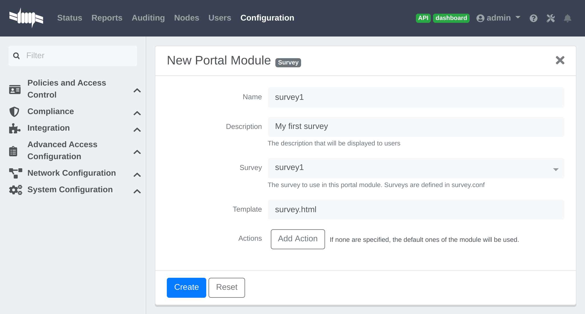
Add the survey to an existing Portal Module (Choice, Chained or Root) or create a New Root Module dedicated for the survey:
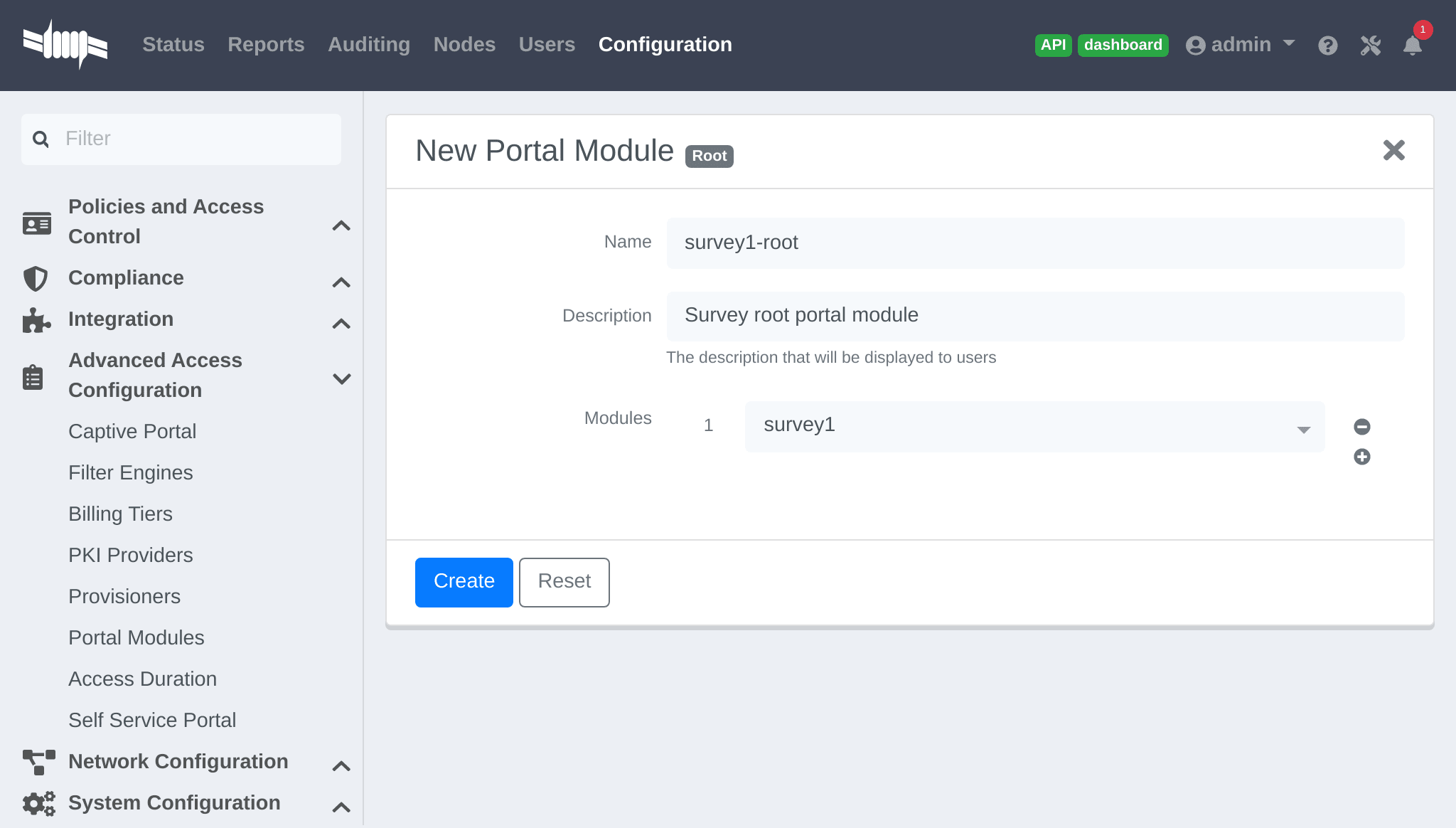
In "Policies and Access Control → Connection Profiles → Name of the profile", ensure the correct "Root Portal Module" is selected.
13.2.4. Explore the collected data
The data collected from the example survey is stored in the survey_survey1
database table. Create a Report for the survey in
/usr/local/pf/conf/report.conf and add the following parameters:
[survey1]description=My first survey reportbase_table=survey_survey1columns=firstname as "Firstname", lastname as "Lastname", preferred_sandwich as "Preferred Sandwich", gender as "Gender"
/usr/local/pf/bin/pfcmd configreload hard
Refer to the Reports section of this document for advanced configuration.
13.2.5. Cleaning up
Once configured, optionally for security, it is recommended to revoke the
CREATE and ALTER privileges from the pf user. The MySQL root user must
be used to REVOKE these privileges.
Access the MYSQL CLI as the root user:
mysql -uroot -p
From the MySQL CLI revoke the privileges:
REVOKE CREATE,ALTER ON pf.* FROM 'pf'@'%';REVOKE CREATE,ALTER ON pf.* FROM 'pf'@'localhost';FLUSH PRIVILEGES;
root password was only provided during Configuration and
not stored on disk.13.3. Self Service - Device Registration
Once a user is registered they can self-register any device on the Portal by entering a MAC address that is matched with an authorized device list through Fingerbank. The device is registered to the user and can be assigned into a specific category.
https://YOUR_PORTAL_HOSTNAME/device-registration.Device registration page is disabled by default. To enable it, configure a self service policy and assign it to a connection profile.
A self-service portal policy can be configured in Configuration → Advanced Access Configuration → Self Service Portal. Define the behavior by either modifying the default policy, or creating a new policy. If the "Role to assign" is left empty, the role of the user that is registering the device will be reused. Optionally select one or more "Allowed OS" to restrict which operating systems can be registered - as it may be useful to only allow gaming devices.
In Configuration → Policies and Access Control → Connection Profiles, assign the "Self service policy", then click Save.
portal listening daemon may need to be added to the management
interface for the "self service portal" to be accessible.13.4. Self Service - Status Page
Once a user is registered they can self-service and manage all their own devices on the Portal. Devices can be unregistered, reported as stolen (trigger a "LOST of Stolen" Security Event). Local users which are defined in the PacketFence database can manage their password.
By default all users can manage all their own devices through the self-service portal. In Configuration → Advanced Access Configuration → Self Service Portal, choose a Self Service Portal, specify the "Self Service Portal → Allowed roles", then click Save.
Status page is available by default, even if a self service policy is not configured. Optionally, it can be disabled in all but the PacketFence management network (registration, isolation, inline) by enabling Status URI only on management interface in Configuration → Advanced Access Configuration → Captive Portal.
In Configuration → Policies and Access Control → Connection Profiles, assign the "Self service policy", then click Save.
portal listening daemon may need to be added to the management
interface for the "self service portal" to be accessible.13.5. Passthroughs
Passthroughs allow access from users confined inside the registration network to specific resources on the outside. An example is to allow clients on the Captive Portal access to an external password reset server.
Passthroughs can be done with either DNS resolution and iptables, or with Apache’s mod_proxy module, or both. A domain configured for both gives priority to DNS passthroughs.
In Configuration → Network Configuration → Networks → Fencing, enable "Passthrough", then click Save.
Then run the following commands so that passthroughs become effective:
/usr/local/pf/bin/pfcmd configreload hard/usr/local/pf/bin/pfcmd service pfdns restart
13.5.1. DNS passthroughs
pfdns must listen only on the VIP. In
Configuration → System Configuration → Cluster, enable "pfdns on VIP
only", then click Save.In Configuration → Network Configuration → Networks → Fencing → Passthroughs, add passthroughs with the format:
-
example.com: opens TCP ports 80 and 443 for example.com -
example.com:1812: opens TCP and UDP port 1812 for example.com -
example.com:tcp:1812: opens TCP port 1812 for example.com -
example.com:udp:1812: opens UDP port 1812 for example.com -
*.example.com:tcp:443: opens TCP port 443 all subdomains for example.com (ex: www.example.com, secure.example.com) -
example.com,example.com:udp:1812,example.com:udp:1813: opens TCP ports 80 and 443, UDP port 1812, UDP port 1813 for example.com
When pfdns receives a DNS request for a passthrough domain it will
forward the unaltered DNS record for the FQDN instead of a response for the
Captive Portal. An ipset entry will be added to permit the device to
access the real external IP address for the FQDN via iptables routing.
13.5.2. Apache mod_proxy passthroughs
mod_proxy does not support non-HTTP (including HTTPS) protocols.In Configuration → Network Configuration → Networks → Fencing, add a comma-separated list of FQDNs in "Proxy Passthroughs", including wildcard domains like *.example.com. Only TCP port 80 is used, so do not specify ports. Click Save.
When pfdns receives a DNS request it will respond with the IP
address of the Captive Portal, and when the device makes a HTTP request on the
Captive Portal for a FQDN that has a configured passthrough the request is
forwarded through mod_proxy.
13.6. Proxy Interception
Proxy requests can be intercepted and forwarded to the Captive Portal. This only works on Layer-2 networks where PacketFence is the default gateway.
In Configuration → Network Configuration → Networks → Fencing, enable "Proxy Interception". Add all the ports to intercept in "Proxy Interception Port", then click Save.
/etc/hosts to resolve the FQDN of the Captive Portal to the IP
address of the registration interface.13.7. Parking Devices
Idle devices (ex: unregistered students) consume resources and generate unnecessary load on the Captive Portal and registration DHCP server.
In large registration networks Parking can be used to provide a longer lease and provide a lightweight Captive Portal that minimizes resource consumption. When a device is parked the Captive Portal provides a message to the user explaining the device is unregistered and has exceeded the parking threshold, and a button to unpark the device.
In Configuration → Network Configuration → Networks → Device Parking,
set the "Parking Threshold" (seconds). A value of 21600 / 6 hours is
suggested. If a device is idle in the registration network for more than 6
hours, Security Event 1300003 (see below) will be triggered and the device
will be parked.
Optionally the lease length (seconds) can also be set in "Parking lease length". If the device is parked with a "Parking lease length" of 1 hour, then immediately unparked, the next detection will occur in 1 hour, even if the "Parking threshold" is a lower value.
13.7.1. Security Event 1300003
In Configuration → Compliance → Security Events, choose Security Event 1300003, configure how the event is handled when a device is parked:
-
In "Event Actions" add actions with the predefined ones (ex:
Email administratororExecute script). -
In "Event Actions → Isolate → Role while isolated" set the destination
role (VLAN) of the user. Leave as
registrationunless a dedicated role is needed for parking. - In "Event Actions → Isolate → Template to use" set the template used in the registration Portal, not the template used for parking. To use the non-parking portal disable "Show parking portal" in Configuration → Network Configuration → Networks → Device Parking.
- In "Grace" set the amount of grace time between two parking security events. Once a device is unparked, wait at least this amount of time for the user to register before re-triggering the Security Event.
14. Advanced Access Configuration
14.1. Connection Profiles
PacketFence provides a default connection profile. The follow parameters are important to configure whether the default connection profile is used or a new one is created:
Redirect URL under Configuration → Policies and Access Control → Connection Profile → Profile Name
For some browsers, it is preferable to redirect the user to a specific URL
instead of the URL originally intended to visit. For these browsers,
the URL defined in redirecturl will be where the user is redirected. Affected
browsers are Firefox 3 and later.
IP under Configuration → Advanced Access Configuration → Captive portal.
This IP is used as the web server that hosts the
common/network-access-detection.gif which is a pixel-gif used to
detect network access. The IP cannot be a domain name since it is used during
Registration and Isolation where DNS is black-holed. Allow users to reach the PacketFence server with the PacketFence LAN IP.
In some cases, a different captive portal may be presented (see below for the available customizations) according to the SSID, the VLAN, the switch IP/MAC or the URI the client connects to. To do so, PacketFence uses the concept of connection profiles to provide this possibility.
When configured, connection profiles will override default values. When no values are configured in the profile, PacketFence will use the values from the "default" connection profile.
Below the different configuration parameters for each connection profile are
provided. The only mandatory parameter is "filter", otherwise, PacketFence will
not be able to correctly apply the connection profile. The parameters are set in
/usr/local/pf/conf/profiles.conf:
[profilename1]description = the description of the connection profilefilter = the name of the SSID or the VLAN to apply the profilesources = a comma-separated list of authentications sources (IDs) to use
Connection profiles should be managed from the admin interface - from the Configuration → Policies and Access Control → Connection Profiles section. Adding a new connection profile will make a copy of the default templates - which can then be modified as desired.
Filters under Configuration → Policies and Access Control → Connection Profile → Profile Name → Filters
Connection TypeNetworkNode RolePortRealmSSIDSwitchSwitch PortURIVLANTime period
Example with common filters:
- SSID: Guest-SSID
- VLAN: 100
- Time period: wd {Mon Tue} hr {1pm-3pm} — See https://metacpan.org/pod/release/PRYAN/Period-1.20/Period.pm
- Switch Port: <SwitchId>-<Port>
- Network: IP address or Network CIDR
Advanced filter under Configuration → Policies and Access Control → Connection Profile → Profile Name → Advanced Filter
This section defines how to create an advanced filter to match specific attributes.
The following attributes are supported:
autoregstatusbypass_vlanbandwidth_balanceregdatebypass_roledevice_classdevice_typedevice_versiondevice_scorepidmachine_accountcategorymaclast_arplast_dhcpuser_agentcomputernamedhcp_fingerprintdetect_datevoipnotestime_balancesessioniddhcp_vendorunregdatefingerbank_info.device_namefingerbank_info.device_fqfingerbank_info.device_hierarchy_namesfingerbank_info.device_hierarchy_idsfingerbank_info.scorefingerbank_info.versionfingerbank_info.mobileradius_request.User-Nameradius_request.NAS-IP-Addressradius_request.NAS-Port-Id
connection_sub_typeconnection_typeswitchportvlanssiddot1x_usernamerealmmachine_account
&& and|| or!= is not equal== equal() group precedence
__NULL__ the value is NULL in the database
14.1.1. Examples
Match machine authentication on secure wireless ssid:
machine_account != "" && connection_type == Wireless-802.11-EAP
Match machine authentication from a previous connection and is connected on a secure ssid:
machine_account != "" && ssid == Secure
Match user authentication and machine authentication on a secure ssid:
last_connection_type == "Wireless-802.11-EAP" && machine_account != "" &&last_dot1x_username !~ "^host/"
Match user authentication without machine authentication on a secure ssid:
last_connection_type == "Wireless-802.11-EAP" && ( machine_account == "" ||machine_account == \\__NULL__ ) && last_dot1x_username !~ "^host/"
Match without machine authentication (BYOD):
machine_account == \\__NULL__
Example of attributes that can be filtered:
'radius_request` => {`NAS-Port-Type` => 15,`Service-Type` => 2,`State` => `0x7cfd15627dba0f5a45baee16526652a6',`Called-Station-Id` => `00:8e:73:5d:f6:9e',`FreeRADIUS-Proxied-To` => `127.0.0.1',`Realm` => `null',`EAP-Type` => 26,`NAS-IP-Address` => `172.30.255.13',`NAS-Port-Id` => `GigabitEthernet1/0/30',`SQL-User-Name` => `gwten',`Calling-Station-Id` => `00:11:22:33:44:55',`PacketFence-Domain` => `ZAYM',`Cisco-AVPair` => `service-type=Framed',`User-Name` => `zaym',`Event-Timestamp` => `Aug 15 2019 17:10:03 BST',`EAP-Message` => `0x024700061a03',`Framed-IP-Address` => `172.30.250.149',`NAS-Port` => 50130,`Stripped-User-Name` => `gwten',`Framed-MTU` => 1500},'autoreg` => `yes','last_port` => `37','device_class` => `Windows OS','bandwidth_balance` => undef,'bypass_role` => undef,'device_type` => `Windows OS','pid` => `gwten','dhcp6_enterprise` => `','last_seen` => \[`NOW()'],'dhcp6_fingerprint` => `','category` => `Wire','mac` => `00:11:22:33:44:55','portal` => `Wire','eap_type` => 26,'last_dhcp` => `0000-00-00 00:00:00','user_agent` => `ccmhttp','computername` => `zamtop','dhcp_fingerprint` => `1,15,3,6,44,46,47,31,33,121,249,43','detect_date` => `2019-08-15 15:33:30','last_vlan` => `0','last_connection_sub_type` => 26,'fingerbank_info` => {`device_fq` => `Operating System/Windows OS',`device_name` => `Windows OS',`version` => `',`score` => `73',`mobile` => 0,`device_hierarchy_names` => [`Windows OS',`Operating System'],`device_hierarchy_ids` => [1,16879]},'bypass_role_id` => undef,'last_role` => `Wire','dhcp_vendor` => `MSFT 5.0','unregdate` => `2019-08-15 20:10:04','last_switch` => `172.20.20.1','auto_registered` => 1,'__from_table` => 1,'source` => `Wire','last_ifDesc` => `GigabitEthernet1/0/30','device_version` => `','status` => `reg','bypass_vlan` => undef,'regdate` => `2019-08-15 17:10:04','last_dot1x_username` => `zayme','tenant_id` => `1','category_id` => `166','machine_account` => `','last_connection_type` => `Ethernet-EAP','last_ssid` => `','realm` => `null','last_ip` => `172.20.20.2','device_score` => `73','last_arp` => `0000-00-00 00:00:00','last_start_timestamp` => `1565885356','stripped_user_name` => `zayme','__old_data` => {`autoreg` => `yes',`device_class` => `Windows OS',`bandwidth_balance` => undef,`bypass_role` => undef,`device_type` => `Windows OS',`pid` => `gwten',`dhcp6_enterprise` => `',`last_seen` => `2019-08-15 16:09:16',`dhcp6_fingerprint` => `',`category` => `Wire',`mac` => `00:11:22:33:44:55',`last_dhcp` => `0000-00-00 00:00:00',`user_agent` => `ccmhttp',`dhcp_fingerprint` => `1,15,3,6,44,46,47,31,33,121,249,43',`computername` => `zamtop',`detect_date` => `2019-08-15 15:33:30',`bypass_role_id` => undef,`dhcp_vendor` => `MSFT 5.0',`unregdate` => `2019-08-15 20:09:16',`device_version` => `',`status` => `reg',`bypass_vlan` => undef,`regdate` => `2019-08-15 17:09:16',`category_id` => `166',`tenant_id` => `1',`machine_account` => undef,`last_arp` => `0000-00-00 00:00:00',`device_score` => `73',`voip` => `no',`device_manufacturer` => `Toshiba',`notes` => `AUTO-REGISTERED',`time_balance` => undef,`sessionid` => undef},'voip` => `no','device_manufacturer` => `Toshiba','notes` => `AUTO-REGISTERED','time_balance` => undef,'last_switch_mac` => `00:8e:73:5d:f6:9e','sessionid` => undef,'last_start_time` => `2019-08-15 16:09:16'
PacketFence uses Apache for its captive portal, administration interface and
Web services. The PacketFence Apache configuration is located in
/usr/local/pf/conf/httpd.conf.d/.
purposes:
-
httpd.admin: used to manage PacketFence admin interface -
httpd.portal: used to manage PacketFence captive portal interface -
httpd.webservices: used to manage PacketFence webservices interface -
httpd.aaa: used to manage incoming RADIUS requests
These files are dynamically generated with Perl and services are only activated on the network interfaces needed for each purpose.
The other files in this directory are managed by PacketFence using templates, so it is easy to modify these files based on the configuration. SSL is enabled by default to secure access.
During installation self-signed certificates will be created in
/usr/local/pf/conf/ssl/ (server.key and server.crt). The
certificates can be replaced anytime by either a 3rd-party or existing wildcard
certificate without issue. Please note that the CN (Common Name) needs to be
the same as the one defined in the PacketFence configuration file
/usr/local/pf/conf/pf.conf.
14.1.2. Reuse 802.1X credentials
In certain circumstances - for example to show an AUP after a successful
802.1X connection - "SSO emulation" may be used so that users do not need
to re-enter their credentials on the portal after having entered them during
802.1X EAP. The connection profile option Reuse 802.1X credentials can be
enabled for this purpose. The username used during the 802.1X connection will
be reused with the different authentication sources to recompute the role from
the portal.
As a security precaution, this option will only reuse 802.1X credentials if
there is an authentication source matching the provided realm. This means, when
users use 802.1X credentials with a domain part (username@domain,
domain\username), the domain part needs to be configured as a realm under
the RADIUS section and an authentication source needs to be configured for that
realm. When users do not use 802.1X credentials with a domain part, only the NULL
realm will be matched IF an authentication source is configured for it.
14.2. Filter Engine Macros
Filter engines support the use of macros in the text field:
uclcjoinsubstrmacToEUI48random_from_rangelogreplaceBuildFromMatch
14.2.1. uc
Upper case string.
Example:
PacketFence-UserName = ${uc($radius_request.Calling-Station-Id)}
assigns the upper case value of Calling-Station-Id to PacketFence-UserName.
Calling-Station-Id = "00:10:7f:38:89:9d" ->PacketFence-UserName = "00:10:7F:38:89:9D"
14.2.2. lc
Lower case string.
Example:
PacketFence-UserName = ${lc($radius_request.User-Name)}
assigns the lower case value of User-Nam to PacketFence-UserName.
User-Name = "ZAMMIT" -> PacketFence-UserName = "zammit"
14.2.3. join
Join strings.
Example:
PacketFence-UserName = ${join(":",$radius_request.User-Name,"Super")}
assign the joined string of the values and separator to PacketFence-UserName.
User-Name = "bobey" -> PacketFence-UserName = "bobey:Super"
14.2.4. substr
A part of a string.
Example:
PacketFence-UserName = ${substr($radius_request.User-Name,0, 5)}
assigns the first 6 characters of a string to PacketFence-UserName.
User-Name = "ZammitLudovic" -> PacketFence-UserName = "Zammit"
14.2.5. macToEUI48
EUI48 format of a MAC address.
Example:
PacketFence-UserName = ${macToEUI48($radius_request.Calling-Station-Id)}
assigns the EUI48 MAC address to PacketFence-UserName.
Calling-Station-Id = "00:10:7f:38:89:9d" ->PacketFence-UserName = "00-10-7F-38-89-9D"
14.2.6. random_from_range
A random integer between a range.
Example:
Session-Timeout = ${random_from_range("10620..12600")}
assigns a random integer between 10620 and 12600 to Session-Timeout.
Session-Timeout = 11343
14.2.7. log
Log a message in packetfence.log.
Example:
PacketFence-UserName = ${log($radius_request.User-Name." logged")}
logs the value of the RADIUS request attribute User-Name appended with " logged".
User-Name = "zammit" -> "Zammit logged"
14.2.8. replace
Replace a string or character.
Example:
PacketFence-UserName = ${replace($radius_request.User-Name,"z","r")}
replace the character "z" by the character "r" from User-Name and assign it to PacketFence-UserName.
User-Name = "zabbit" -> PacketFence-UserName = "rabbit"
14.2.9. BuildFromMatch
Regular expression match on a string or character.
Example:
TLS-Stripped-UserName =${BuildFromMatch($radius_request.TLS-Client-Cert-Common-Name,"^[^@]+","$0")}
extract the value from TLS-Client-Cert-Common-Name before the @ sign and assign it to TLS-Stripped-UserName.
TLS-Client-Cert-Common-Name = "zammit@packetfence.org" ->TLS-Stripped-UserName = "zammit"
14.3. VLAN Filters
Filters can be defined directly in the portion of code that re-evaluates the VLAN or performs API calls when a RADIUS request is received. These filters can be defined in Configuration → Advanced Access Configuration → Filter engines.
These rules are available in different scopes:
IsolationRoleRegistrationRoleRegisteredRoleInlineRoleAutoRegisterNodeInfoForAutoReg
And can be defined using different criteria:
node_info.attribute (like node_info.status)switchifIndexmacconnection_typeusernamessidtimeowner.attribute (like owner.pid)radius_request.attribute (like radius_request.Calling-Station-Id)
Default VLAN filters are defined in the configuration that can be used to achieve the following goals:
- EXAMPLE_Reject_between_11am_2pm
-
prevent a registered device from connecting when its role is default, the SSID is SECURE, the current time is between 11am and 2pm, from Monday to Friday.
- EXAMPLE_Trigger_event_if_user
-
create a security event if the SSID is OPEN and the owner is igmout (the security event needs to have a custom trigger with the value 12345).
- EXAMPLE_Autoregister_if_user
-
autoregister the device and assign the role staff to each device if the username is igmout.
- EXAMPLE_Autoregister_windows_devices
-
autoregister all Windows devices and assign them the default role.
- EXAMPLE_Reject_specific_MAC
-
filter a MAC address and reject it by assigning the REJECT role.
- EXAMPLE_Detect_VOIP
-
set Avaya and Polycom as phones by matching vendor MAC and set to default role.
- EXAMPLE_Reject_User_Unless_Machine
-
refuse user authentication without prior machine authentication.
- EXAMPLE_Autoregister_Printer_Scanner
-
autoregister printers and scanners and add a note.
Several examples on how to use and define filters are included in
/usr/local/pf/conf/vlan_filters.conf.defaults.
14.4. RADIUS Filters
Filters can be defined directly in the portion of code that returns RADIUS attributes or performs API calls when a RADIUS request is received. These filters can be defined in Configuration → Advanced Access Configuration → Filter engines.
We added the ability to specify filters directly in the portion of code that return RADIUS attributes or do a call to the API. These filters can be defined in Configuration → Advanced Access Configuration → Filter engines.
These rules are available in thoses scopes:
returnRadiusAccessAccept: return the answer for a device's accessreturnAuthorizeRead: return the answer for the switch read login accessreturnAuthorizeWrite: return the answer for the switch write login accessreturnAuthorizeVoip: return the answer for a VoIP devicepreProcess: manipulate the RADIUS context (example: add custom attributesto the request)
packetfence.authorize: call the RADIUS filter in the packetfence authorizesectionpacketfence.authenticate: call the RADIUS filter in the packetfenceauthenticate sectionpacketfence.pre-proxy: call the RADIUS filter in the packetfence pre-proxysectionpacketfence.post-proxy: call the RADIUS filter in the packetfencepost-proxy sectionpacketfence-tunnel.authorize: call the RADIUS filter in thepacketfence-tunnel authorize sectionpacketfence.preacct: call the RADIUS filter in the packetfence preacct sectionpacketfence.accounting: call the RADIUS filter in the packetfenceaccounting sectioneduroam.authorize: call the RADIUS filter in the eduroam accounting sectioneduroam.pre-proxy: call the RADIUS filter in the pre-proxy accounting sectioneduroam.post-proxy: call the RADIUS filter in the post-proxy accountingsectioneduroam.preacct: call the RADIUS filter in the eduroam preacct section
All the packetfence. and eduroam. scopes are explained in
/user/local/pf/conf/radius_filters.conf.
And can be defined using different criteria like:
node_info.attribute (like node_info.$attribute)switchifIndexmacconnection_typeusernamessidtimeowner.attribute (like owner.$attribute)radius_request.attribute (like radius_request.$attribute)security_eventuser_rolevlan
Default RADIUS filters are defined in the configuration that can be used to achieve the following goals:
- EXAMPLE_Ethernet-EAP-Accept
-
returns Access-Accept (with Cisco-AVPair attribute) when the connection is Ethernet-EAP and no security event exists.
- EXAMPLE_Session-timeout_Idle-Timeout_Terminate_action
-
filter on the switch IP addresses and add the Session-Timeout (with a value between 10620 and 12600), the Idle-Timeout and Terminate-Action RADIUS attributes.
- EXAMPLE_ipad_by_name
-
use Fingerbank to target specific devices (Apple iPad) and add Cisco ACL(s) to them.
- EXAMPLE_eap-tls-preProcess
-
create RADIUS attributes that will be used internally (like authentication rules). Add the TLS-Stripped-UserName RADIUS attribute in the request which can be used in the authentication/administrations rules.
Several examples on how to use and define filters are included in
/usr/local/pf/conf/radius_filters.conf.defaults.
14.5. Advanced LDAP Authentication
14.5.1. LDAPfilter actions
LDAPfilter actions override the internal LDAP filter that PacketFence creates internally (uid=$username) so a custom filter can be created that matches specific needs.
Example user search that checks permission based on some criteria:
(&(|(cn=${radius_request.Stripped-User-Name})(cn=${radius_request.User-Name}))(|(permitWifi=*)(grade=staff)(memberOf=CN=WifiGroup,OU=Security Groups,DC=ad,DC=zammitcorp,DC=com)))
14.5.2. Action set_role_on_not_found
set_role_on_not_found defines a role if the rule does not match.
Adding the action set_role_on_not_found = REJECT will reject the device if
the LDAP filter match returns empty. On the other hand, if a filter match is
found then the set_role action is applied.
14.5.3. Action role_from_source
role_from_source checks if the LDAP attribute exists, if so it is added
in the ldap_attribute context (available in the RADIUS filters).
Example that takes the LDAP attribute customRadius value and adds it in the
RADIUS answer. In the authentication rule add an action "Role from source" to
customRadius. Next create a RADIUS filter that will add the custom RADIUS
attributes:
[IF_SET_ROLE_FROM_SOURCE]status=enabledanswer.0=reply:Packetfence-Raw = $ldap_attribute.customRadiustop_op=anddescription=If the role has been computed from the actionset_role_from_source then return the value of the role as a RADIUS attributescopes=returnRadiusAccessAcceptradius_status=RLM_MODULE_OKmerge_answer=nocondition=action == "set_role_from_source"
customRadius:Airespace-Interface-Name=internet and
customRadius:Aruba-User-Vlan=666.14.5.4. Append search attributes LDAP filter
This option will add an AND condition (&) to the LDAP filter generated by PacketFence.
Example of an LDAP filter that is generated by PacketFence:
(&(|(sAMAccountName=%{User-Name})(sAMAccountName=%{Stripped-User-Name})(cn=%{User-Name})(cn=%{Stripped-User-Name})(sAMAccountName=%{%{Stripped-User-Name}:-%{User-Name}})))
If an LDAP filter is manually defined as:
(|(memberOf=CN=Staff,OU=Security Groups,DC=ad,DC=zammitcorp,DC=com)(wifi=enabled))
The filter will be combined and generated as:
(&(|(sAMAccountName=%{User-Name})(sAMAccountName=%{Stripped-User-Name})(cn=%{User-Name})(cn=%{Stripped-User-Name})(sAMAccountName=%{%{Stripped-User-Name}:-%{User-Name}}))(|(memberOf=CN=Staff,OU=Security Groups,DC=ad,DC=zammitcorp,DC=com)(wifi=enabled)))
If the "Search Attributes" feature is not required, this will still store the users` DN in the PacketFence-UserDN attribute.
14.5.5. basedn condition
This condition overrides the default basedn in the LDAP source and will
test if an object is in a specific OU.
14.6. Advanced Realm Configuration
Multiple realms can be defined to select which domain is used to authenticate users.
A Realm is defined with a regex in order to match multiple formats.
For example in the ZAMMITCORP realm we define the regex like this:
.*\.zammitcorp.com\.com$
Thus in the case of username mickey@le.zammitcorp.com, the realm is defined as le.zammitcorp.com - which is included in the RADIUS request - and the user is mapped with the ZAMMITCORP realm.
15. Advanced RADIUS Configuration
FreeRADIUS configuration steps. RADIUS server is required for network access in WPA2-Enterprise (Wireless 802.1X), MAC authentication and Wired 802.1X. RADIUS authenticates users and devices, then pushes roles or VLAN attributes to network equipment.
15.1. Local Authentication
Add user entries to /usr/local/pf/raddb/users file:
username Cleartext-Password := "password"
For RADIUS authentication issues, see RADIUS Debugging in the Troubleshooting section for debug commands and log analysis.
15.2. Authentication against Active Directory (AD)
For EAP-PEAP authentication with Microsoft Active Directory, refer to Active Directory documentation in Authentication Mechanism section.
15.3. EAP Authentication against OpenLDAP
For 802.1X authentication against OpenLDAP, define LDAP connection in
/usr/local/pf/raddb/modules/ldap and ensure user password is
NTHASH or clear
text.
ldap openldap {server = "ldap.zammitcorp.com"identity = "uid=admin,dc=zammitcorp,dc=com"password = "password"basedn = "dc=district,dc=zammitcorp,dc=com"filter = "(uid=%{mschap:User-Name})"ldap_connections_number = 5timeout = 4timelimit = 3net_timeout = 1tls {}dictionary_mapping = ${confdir}/ldap.attrmapedir_account_policy_check = nokeepalive {# LDAP_OPT_X_KEEPALIVE_IDLEidle = 60# LDAP_OPT_X_KEEPALIVE_PROBESprobes = 3# LDAP_OPT_X_KEEPALIVE_INTERVALinterval = 3}}
Next in /usr/local/pf/raddb/sites-available/packetfence-tunnel
add in the authorize section:
authorize {suffixntdomaineap {ok = return}filesopenldap}
15.4. EAP Guest Authentication on Email, Sponsor and SMS Registration
This section will allow local credentials created during guest registration to be used in 802.1X EAP-PEAP connections.
plaintext or ntlm as the "Database passwords
hashing method" to make it work.First create a guest SSID with the guest access you want to use (Email,
Sponsor or SMS, …) and activate Create local account on that source.
At the end of the guest registration, PacketFence will send an email with the credentials for Email and Sponsor and SMS.
To enable this feature, in the admin interface go to Configuration → System Configuration → RADIUS → General and enable `Authenticate against local users database'. Once saved, restart the radiusd service.
15.5. EAP Local User Authentication
The goal here is to use the local user to authenticate 802.1X device.
To enable this feature, in the admin interface go to Configuration → System Configuration → RADIUS → General and enable `Authenticate against local users database'. Once saved, restart the radiusd service.
plaintext or ntlm to be
able to work.15.6. Limit Brute Force EAP Authentication
This section will allow you to limit a brute force attack and prevent the locking of Active Directory accounts.
Edit /usr/local/pf/conf/radiusd/packetfence-tunnel
# Uncomment the following lines to enable this featurepacketfence-control-ntlm-failurepacketfence-cache-ntlm-hit
By default it will reject for 5 minutes a device that has been rejected
twice in the last 5 minutes.
Fell free to change the default values in raddb/policy.d/packetfence and
in raddb/mods-enabled/cache_ntlm
15.7. Testing
Test your setup with radtest using the following command and make sure you
get an Access-Accept answer:
# radtest dd9999 Abcd1234 localhost:18120 12 testing123Sending Access-Request of id 74 to 127.0.0.1 port 18120User-Name = "dd9999"User-Password = "Abcd1234"NAS-IP-Address = 255.255.255.255NAS-Port = 12rad_recv: Access-Accept packet from host 127.0.0.1:18120, id=74, length=20
15.8. RADIUS Accounting
RADIUS Accounting is usually used by ISPs to bill clients. In PacketFence, we are able to use this information to determine if the node is still connected, how much time it has been connected, and how much bandwidth the user consumed.
PacketFence uses RADIUS Accounting to display Online/Offline status in webadmin in Nodes menu.
15.8.1. IP log updates
If you send the IP address of nodes in accounting data and want to update
iplog entries of your nodes, you can enable Update the iplog using the
accounting setting from Configuration → System configuration → Main
configuration → Advanced.
15.8.2. Security Events
Using PacketFence, it is possible to add security events to limit bandwidth abuse. The format of the trigger is very simple:
Accounting::[DIRECTION][LIMIT][INTERVAL(optional)]
Let’s explain each chunk properly:
-
DIRECTION: You can either set a limit to inbound(IN), outbound(OUT), or total(TOT) bandwidth -
LIMIT: You can set a number of bytes(B), kilobytes(KB), megabytes(MB), gigabytes(GB), or petabytes(PB) -
INTERVAL: This is actually the time window we will look for potential abuse. You can set a number of days(D), weeks(W), months(M), or years(Y).
Example triggers
- Look for Incoming (Download) traffic with a 50GB/month
-
Accounting::IN50GB1M
- Look for Outgoing (Upload) traffic with a 500MB/day
-
Accounting::OUT500MB1D
- Look for Total (Download + Upload) traffic with a 200GB limit in the last week
-
Accounting::TOT200GB1W
Grace Period
When using such security event feature, setting the grace period is really important. You don’t want to put it too low (ie. A user re-enable his network, and get caught after 1 bytes is transmitted!) or too high. We recommend that you set the grace period to one interval window.
15.9. RADIUS Proxy
RADIUS Proxy is a way to proxy authentication and accounting requests to other radius server(s) based on the realm. Let’s say you want to authenticate users on an Active Directory where there is a NPS server running and you don’t want to join the PacketFence’s server to this domain or in the case you want to integrate PacketFence in a Passpoint setup then this section is for you.
To do that in PacketFence you need first to define the target RADIUS server(s) in Configuration → Policies and Access Control → Authentication Sources, and create the RADIUS source(s) (ZAMMITCORP1 ZAMMITCORP2). In the Source configuration, fill the mandatory fields and add the options to define the home_server in FreeRADIUS. (https://github.com/FreeRADIUS/freeradius-server/blob/v3.0.x/raddb/proxy.conf)
Per example for the RADIUS Source ZAMMITCORP1:
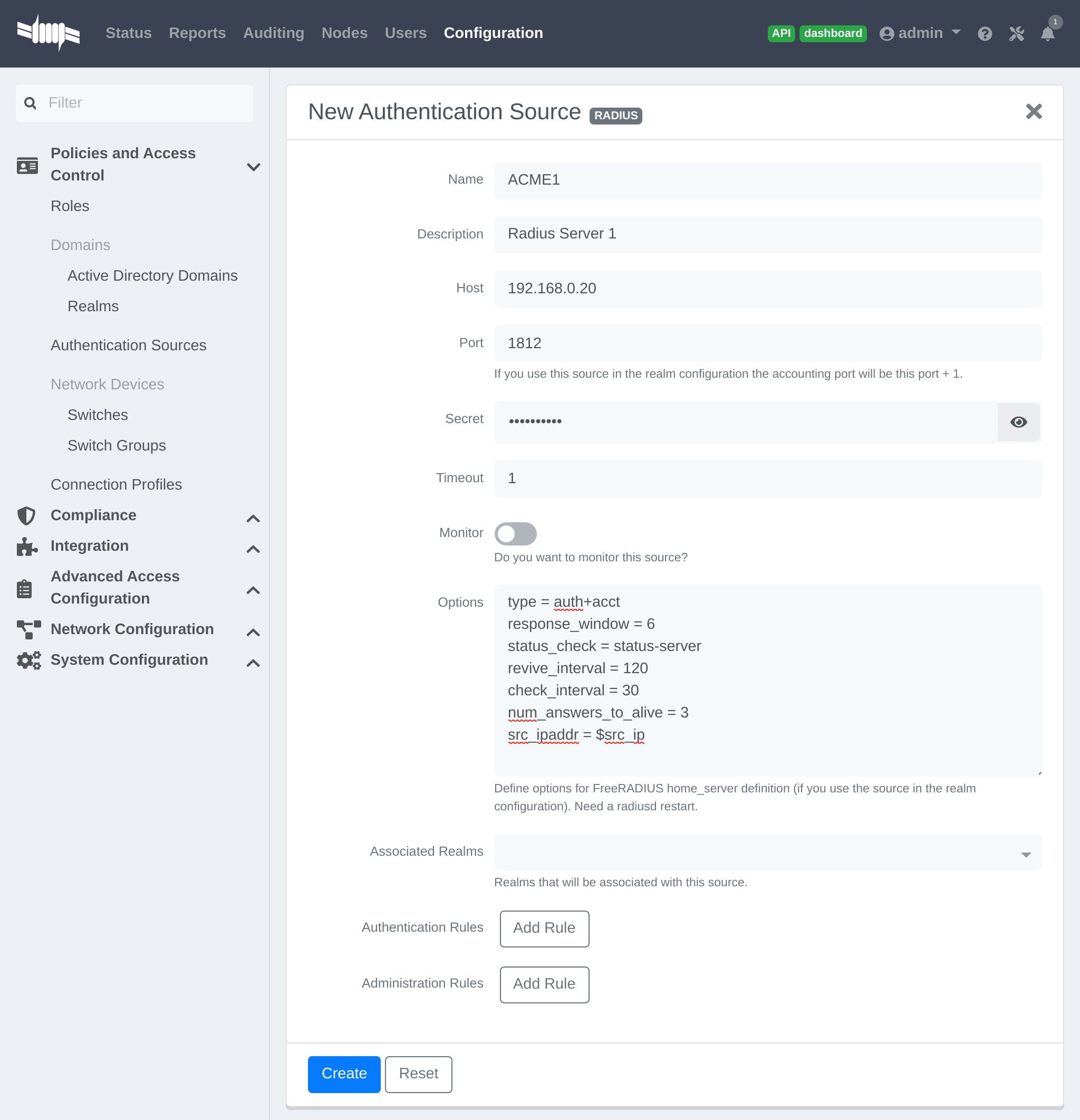
$src_ip is a way to dynamically use the correct source ip address of the system in case of multiples network interfaces.
Next go in Configuration → Policies and Access Control → REALMS, and add a new realm.
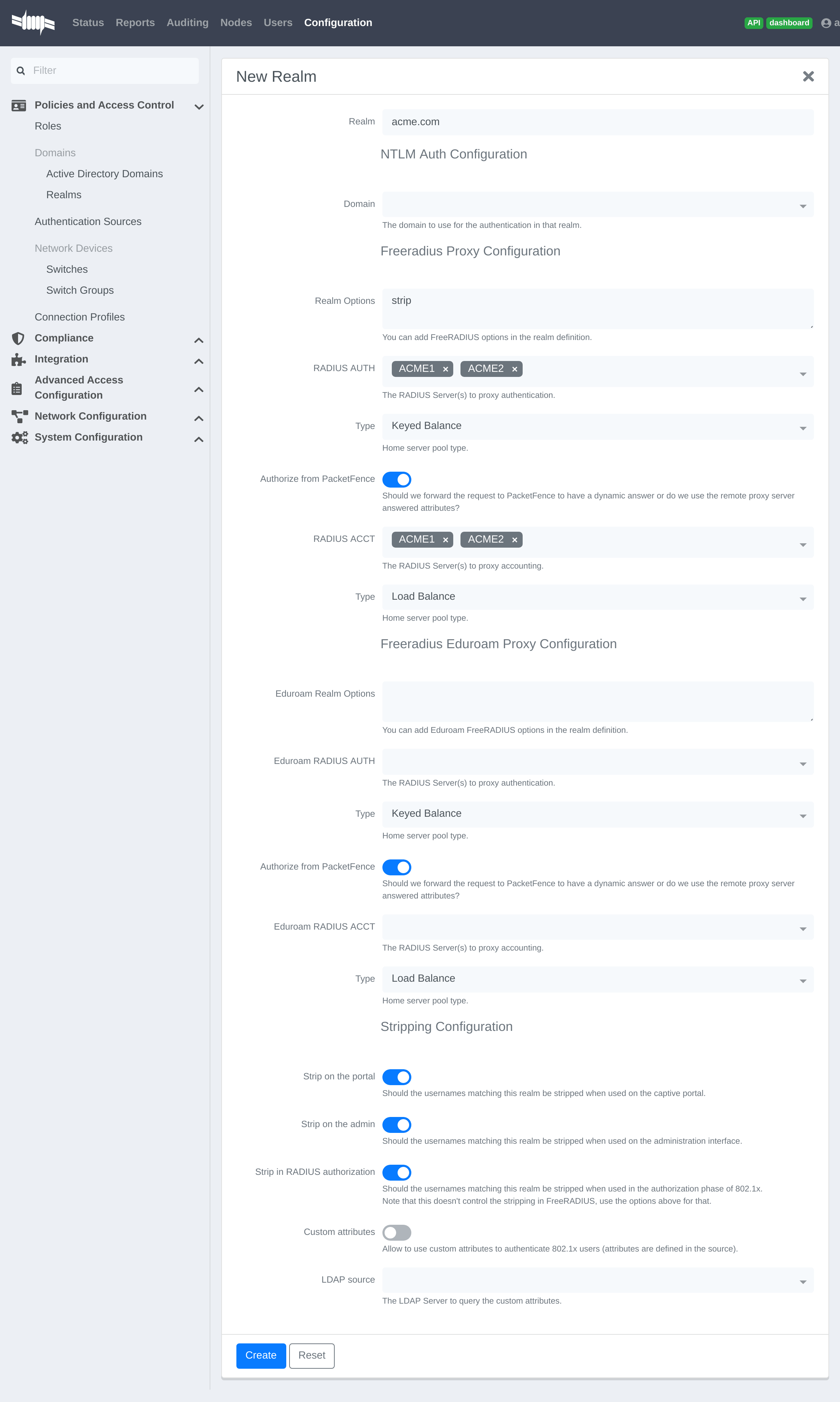
(type definition can be found here https://wiki.freeradius.org/features/Proxy)
Authorize from PacketFence will send the request to PacketFence to compute the role and access duration of the device.
In this case the easiest way to achieve that is to create a Authorization source (with rules), assign this source to a connection profile where you enabled "Automatically register devices" and where you defined a filter like Realm = zammitcorp.com .
Click on Save and restart radiusd service.
/usr/local/pf/bin/pfcmd service radiusd restart
Now when a device connect with the username bob@zammitcorp.com then the authentication and accounting requests will be forwarded to one of the ZAMMITCORP RADIUS servers.
15.9.1. RADIUS Proxy Advanced
In this section we will explain how to proxy RADIUS requests based on an advanced criteria.
First you have to create RADIUS authentication source like above and create for example two realms "to_NPS" and "to_ISE" (associate the RADIUS sources in the REALMs)
Next you have to enable the RADIUS filters in the packetfence.authorize and packetfence.post-proxy scope, to do that you have to go in Configuration → System Configuration → RADIUS → General , and enable "Use RADIUS filters in packetfence authorize" and "Use RADIUS filters in packetfence post-proxy".
After this step restart the packetfence-radiusd-auth service (systemctl restart packetfence-radiusd-auth.service).
Here are some examples of what you can do with the RADIUS filters (the content of the radius_filters.conf file):
Proxy the RADIUS request to the to_NPS realm if the Calling-Station-Id or Colubris-AVPair attribute matches the regex ZAMMITCORP$
[NPS]scopes=packetfence.authorizedescription=to_NPScondition=radius_request.Called-Station-Id =~ "ZAMMITCORP$" ||radius_request.Colubris-AVPair =~ "ZAMMITCORP$"status=disabledmerge_answer=yesanswer.0=control:Proxy-To-Realm = to_NPS
Proxy the RADIUS request the to_ISE realm if the Calling-Station-Id or Colubris-AVPair attribute contains ZAMMITCORP_Admin$ and add the attribute Realm with the value to_ISE in the RADIUS request (can be for example used as a filter in a connection profile)
[ISE]merge_answer=yesstatus=disabledcondition=contains(radius_request.Called-Station-Id, "ZAMMITCORP_Admin") ||contains(radius_request.Colubris-AVPair, "ZAMMITCORP_Admin")scopes=packetfence.authorize,packetfence.post-proxydescription=to_ISEanswer.0=control:Proxy-To-Realm = to_ISEanswer.1=request:Realm = to_ISE
Proxy the RADIUS request to the NULL realm if the Calling-Station-Id or Colubris-AVPair attribute matches the regex Guest$
[NULL]scopes=packetfence.authorizedescription=to_nullstatus=enabledmerge_answer=yescondition=radius_request.Called-Station-Id =~ "Guest$" ||radius_request.Colubris-AVPair =~ "Guest$"answer.0=control:Proxy-To-Realm = NULL
Proxy the RADIUS request to the to_ISE realm if the Calling-Station-Id attribute matches the regex ZAMMITCORP$
[NO_REALM]merge_answer=noscopes=packetfence.authorizestatus=enabledcondition=radius_request.Called-Station-Id =~ "ZAMMITCORP$" &¬_contains(radius_request.User-Name, "@") &¬_contains(radius_request.User-Name, "\\")description=NO_REALManswer.0=control:Proxy-To-Realm = to_ISE
Proxy the RADIUS request to the to_ISE realm if the device role is Employe and the status is registered
[Employe]merge_answer=noscopes=packetfence.authorizestatus=enabledcondition=node_info.category == "Employe" && node_info.status == "reg"description=Employeanswer.0=control:Proxy-To-Realm = to_ISE
/usr/local/pf/conf/radius_filters.conf and after, perform a/usr/local/pf/bin/pfcmd configreload hard
15.10. RADIUS EAP Profiles
RADIUS EAP Profiles allow you to select a specific EAP profile in PacketFence based on the realm of the user.
In this EAP profile you can define:
- Certificates configuration.
- OCSP configuration
- EAP-Fast configuration
- TLS Configuration
And link all these configuration together.
For example the realm ZAMMITCORP.COM needs to use the CA certificate from ZAMMITCORP CA and the other realms need to use the default one.
To do that go in Configuration → System Configuration → RADIUS → SSL Certificates and create a new profile. Next go in Configuration → System Configuration → RADIUS → TLS Profiles and create a new TLS profile and select the Certificate profile created just before. Then create the EAP profile in Configuration → System Configuration → RADIUS → EAP Profiles and create a new EAP profile and select the TLS profile created before (PEAP Profile for exemple)
The last thing to do is to link the EAP profile with your realm configuration, to achieve that go in Configuration → Policies and Access Control → Domains → REALMS and edit the ZAMMITCORP.COM realm (create it if it’s not already the case) then choose the EAP profile you created before in the EAP configuration parameter.
Restart packetfence-radiusd-auth.service to generate the new RADIUS configuration. (systemctl restart packetfence-radiusd-auth.service)
16. Fingerbank Integration
Fingerbank device profiling tool integrates with PacketFence, enabling administrators to trigger security events based on device types, device parents, DHCP fingerprints, DHCP vendor IDs, MAC vendors and browser user agents.
Core integration enables PacketFence to interact with Fingerbank upstream project for daily fingerprint database updates, sharing unknown data for complex algorithm processing, global database integration, and upstream database queries for unknown matches.
Fingerbank is PacketFence’s primary device profiling tool, designed for simple configuration and use. Working PacketFence systems have Fingerbank ready in "local" mode (no upstream interaction).
16.1. Onboarding
Onboarding creates API key for upstream project interaction. Go to "Settings" under "Fingerbank" in PacketFence "Configuration" tab. Follow the process to create and save user/organization-specific API key. Once completed, full Fingerbank features are available.
16.2. Update Fingerbank Database
Updating Fingerbank data is simple. Requires onboarding for upstream interaction. "Update Fingerbank DB" option appears at top of "Fingerbank" menu sections. Process takes 1-2 minutes depending on database size and internet connectivity. Success or error message displayed afterward. "Local" records remain unmodified.
16.3. Submit Unknown Data
The "Submit Unknown/Unmatched Fingerprints" option (available after onboarding) submits unknown fingerprinting data from your network to the upstream Fingerbank project for analysis and global database integration.
16.4. Upstream Interrogation
By default, PacketFence interrogates the upstream Fingerbank project (after onboarding) to fulfill queries with unmatched local results. Unmatched local results may indicate older database version or requirement for complex algorithm processing. This behavior is transparent and configurable via "Settings" under "Fingerbank" in the PacketFence "Configuration" tab.
16.5. Local Entries
Administrators can customize or create records using "Local" entries. Upstream records (DHCP Fingerprint, DHCP Vendor, MAC Vendor, User Agent, Device type, Combination) can be cloned and modified locally. Local records are matched first to override existing ones. Local combinations can match "Local", "Upstream", or both entries for device identification.
16.6. Settings
Fingerbank settings are accessible via "Settings" under "Fingerbank" in the PacketFence "Configuration" tab. Each parameter includes documentation for easier understanding.
16.7. Device change detection
Fingerbank detects potential MAC spoofing when devices change device class (e.g., Windows to printer), triggering security events and potentially isolating endpoints. Example security event ID 1300006 ("Fingerbank device class change") demonstrates this trigger.
This feature is disabled by default. Configure it in Configuration → Compliance → Fingerbank Profiling → Device Change Detection.
Check Enabled to activate this feature. Choose between triggering security events on any device class change or specific changes.
16.7.1. Triggering on any device class change
The easiest detection method triggers on any device class change, firing security events when devices transition between classes. Since some transitions may be normal, add whitelisting via "Device class change whitelist" parameter (e.g., "Windows OS" to "Mac OS X or macOS").
16.7.2. Manual triggers
Instead of detecting all transitions, trigger security events on specific device class transitions. Declare transitions in "Manual device class change triggers".
If device profiling isn’t working, check fingerbank logs as described in Log Files in the Troubleshooting section.
17. Network Devices Anomaly Detection
Starting with version 10, PacketFence integrates network devices anomaly detection capabilities. This means that PacketFence can detect abnormal network activities from devices - that is, if they are talking to a compromised host, if they are deviating from their pristine network profile and more. These capabilities come from the integration of the Fingerbank technology. That is, the Fingerbank Cloud API is responsible for producing pristine network device profiles while the Fingerbank Collector, included in PacketFence, does consume the pristine profiles and does anomaly detection based on its templating engine.
17.1. Creating Network Behavior Policies
A network behavior policy is a template, used by the Fingerbank Collector, to determine if the devices matching the criteria defined in the template ultimately deviate from a normal network usage pattern. You can create new templates from Configuration → Compliance → Network Anomaly Detection.
Network behavior policies can be consumed from PacketFence’s Security Events module.
17.2. Integration with Security Events
After creating a network behavior policy, you can use it from the Security
Events module of PacketFence. From Configuration → Compliance → Security
Events, click on New Security Event.
You can use your policy by first adding a new trigger. The network behavior policy can be selected after defining an internal event on the following attributes:
- fingerbank_blacklisted_ips_threshold_too_high - Fingerbank Collector detected traffic to blacklisted IPs
- fingerbank_blacklisted_ports - Fingerbank Collector detected traffic to blacklisted ports
- fingerbank_diff_score_too_low - Fingerbank Collector detected a network behavior that doesn’t match the known profile
Once done, the appropriate policy can be selected. If you want your entire network policy to be checked in the Security Events module, you must create three triggers - one with each of the attribute listed above together with your appropriate policy selected. You can look at the default security events Fingerbank profile anomaly (1300007) and Fingerbank detected blacklisted communication (1300008) for some examples on how to create customized security events to fulfill your requirements.
18. Intrusion Detection System Integration
18.1. Regex Syslog Parser
You are now able to create syslog parser using regex. This will allow you complex filters and rules to work on data receive via syslog.
Configuring a Regex Syslog Parser
- Enabled - You can enable/disable the parser from running
- Alert Pipe - A previously created alert pipe (FIFO)
- Rules - The list of rules that defines how to match log file entries and what action(s) to take when matching
Regex Syslog Parser Rule
- Name - The name of the rule
- Regex - The regex to match against a log entry. The regex may have named captures which can be used for parameter replacement start a '$'.
- Actions - A list of actions to take when the regex matches
- IP to MAC - Perform automatic translation of IPs to MACs and the other way around
- Last if matches - Stop processing the other rules if this rule matched
Defining Actions
An action have two parts
- method - The name of the action you want to take
- parameter list - The list of parameters you want to provide to the method. Each parameter is separated by a comma. The parameters that are to be replaced by a named capture.
Example Action
Regex -
mac\s*:\s*(?P<mac>[a-zA-Z0-9]{2}(:[a-zA-Z0-9]{2}){5}),notes\s*:\s*(P?<notes>.*)
Action -
modify_node: mac, $mac, notes, $notes
18.2. FortiGate DHCP Parser
PacketFence is able to receive DHCP information from the FortiGate firewall.
On the PacketFence server:
Modify rsyslog configuration to allow incoming UDP packets by uncommenting the
following two lines in /etc/rsyslog.conf:
$ModLoad imudp$UDPServerRun 514
Configure /etc/rsyslog.d/fortigate.conf so it contains the following
which will redirect fortigate log entries and stop further processing of current
matched message (in that case 192.168.40.1 is the ip of the FortiGate):
if $fromhost-ip=='192.168.40.1' then /usr/local/pf/var/fortigate& ~
Make sure the receiving alert pipe (FIFO) exists
mkfifo /usr/local/pf/var/fortigate
Restart the rsyslog daemon
service rsyslog restart
On the FortiGate side make sure to configure the syslog configuration as the following:
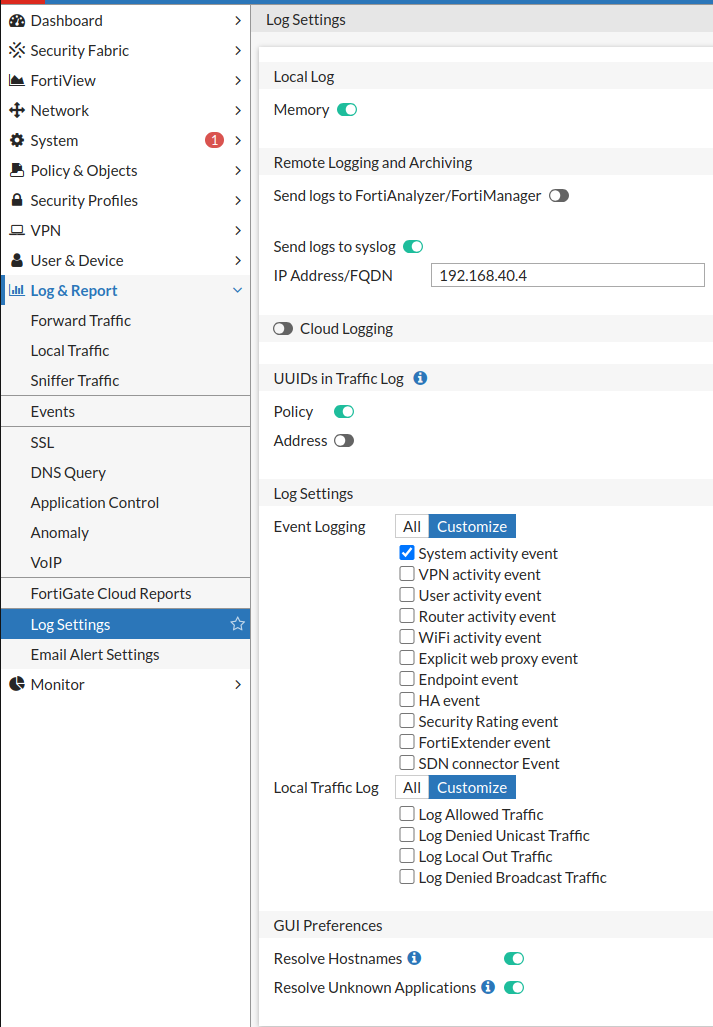
18.3. Suricata IDS
PacketFence already contains a event handler for Suricata. This is an example to raise a security event from a syslog alert on the Suricata SID.
The first step is to create the syslog regex parser and then create the security event.
18.3.1. Syslog regex parser configuration
To create the syslog regex parser you will need to go to Configuration → Integration → Event Handlers → Add a Event Handler → regex
Here is the configuration of the syslog regex parser:
Detector *: SuricataEnabled: checkedAlert pipe: /usr/local/pf/var/suricata (To create the fifo file, do: mkfifo/usr/local/pf/var/suricata)
Rules:
Rule - New:
Name *: ET P2P Kaaza Media desktop p2pnetworking.exeRegex *: (?P<date>\d{2}\/\d{2}\/\d{4}-\d{2}:\d{2}:\d{2}.*?) \[\*\*\]\[\d+:(?P<sid>\d+):\d+\] (?P<message>.*?) \[\*\*\].*(?P<srcip>\d{1,3}(\.\d{1,3}){3}):(?P<srcport>\d+) ->(?P<ip>\d{1,3}(\.\d{1,3}){3}):(?P<port>\d+)Action: trigger_security_event mac, $mac, tid, $sid, type, detectLast if match: uncheckedIP to MAC: checked
Save the regex rule.
You can directly test your rule. In the previous example the parser expect a syslog string like this:
02/26/2017-14:29:00.524309 [**] [1:2000340:10] ET P2P Kaaza Media desktopp2pnetworking.exe Activity [**] [Classification: Potential Corporate PrivacyViolation] [Priority: 1] {UDP} 173.194.7.75:443 -> 1.2.3.4:46742
In order to have a correct match in the rule, you will need to have a valid
iplog entry in the database. Put the string in the test box and then click on
the RUN TEST button, you should get:
Click to see actions for - 02/26/2017-14:29:00.524309 [**] [1:2000340:10] ETP2P Kaaza Media desktop p2pnetworking.exe Activity [**] [Classification:Potential Corporate Privacy Violation] [Priority: 1] {UDP} 173.194.7.75:443-> 1.2.3.4:46742
- ET P2P Kaaza Media desktop p2pnetworking.exe : trigger_security_event('mac', '00:11:22:33:44:55', 'tid', '2000340', 'type', 'detect')
We can see that PacketFence will execute the security event on the MAC address 00:11:22:33:44:55.
18.3.2. Security Event Creation
Now you will need to create the security event with the trigger id '2000340' in order to isolate the device. In order to do so, go to Configuration → Compliance → Security Events → New Security Event
Definition:
Enabled: ONIdentifier: 1500001Description: ET P2P Kaaza MediaAction: Reevaluate Access Action; Log messagePriority: 1
Triggers:
-
Click on the
(+)button - Look for 'detect' in the dropdown list
-
Add the trigger ID: 2000340 and click the
ADDbutton -
Click on the
<button next to 'Select Some Options'
Remediation:
Auto Enable: checkedMax Enables: 2Grace: 5 minutesTemplate: p2p.html
Click on the SAVE button.
Now you will need to restart the pfqueue and the pfdetect services.
/usr/local/pf/bin/pfcmd service pfqueue restart
/usr/local/pf/bin/pfcmd service pfdetect restart
Make sure that you have your pipe file otherwise the process won’t start.
18.4. Security Onion
18.4.1. Installation and Configuration
Security Onion is a Ubuntu-based security suite. The latest installation instructions are available directly from the Security Onion website, https://github.com/Security-Onion-Solutions/security-onion/wiki/Installation
Since a security suite consists of multiple pieces of software tied together, you may be prompted for different options during the installation process. A detailed "Production Deployment" guide can also be found directly from the Security Onion website: https://github.com/Security-Onion-Solutions/security-onion/wiki/ProductionDeployment
18.4.2. PacketFence Integration
Once Security Onion is installed and minimally configured, integration with PacketFence is required to be able to raise security events based on sensor(s) alerts. syslog is used to forward sensor(s) alerts from Security Onion to the PacketFence detection mechanisms.
The simplest way is as follow (based on https://github.com/Security-Onion-Solutions/security-onion/wiki/ThirdPartyIntegration);
On the Security Onion server:
Configure /etc/syslog-ng/syslog-ng.conf by adding the following to
enable sending sguild log entries to PacketFence:
### PacketFence / IDS integration# This line specifies where the sguild.log file is located# -> Make sure to configure the right path along with the right filename (on aSecurity Onion setup, that should be pretty much standard)source s_sguil { file("/var/log/nsm/securityonion/sguild.log"program_override("securityonion_ids")); };# This line filters on the string “Archived Alert”filter f_sguil { match("Archived Alert"); };# This line tells syslog-ng to send the data read to the PacketFencemanagement IP address using UDP 514# -> Make sure to configure the right PacketFence management interface IPaddressdestination d_packetfence_alerts { udp("PACKETFENCE_MGMT_IP" port(514)); };# This line indicates syslog-ng to use the s_sguil source, apply the f_sguilfilter and send it to the d_packetfence_alerts destinationlog { source(s_sguil); filter(f_sguil); destination(d_packetfence_alerts); };
Sending sguild alert output to syslog requires DEBUG to be changed from 1 to 2
under /etc/sguild/sguild.conf
set DEBUG 2
A restart of the sguild daemon is then required
sudo nsm_server_ps-restart
A restart of the syslog-ng daemon is then required
service syslog-ng restart
On the PacketFence server:
Modify rsyslog configuration to allow incoming UDP packets by uncommenting the
following two lines in /etc/rsyslog.conf:
$ModLoad imudp$UDPServerRun 514
Configure /etc/rsyslog.d/securityonion_ids.conf so it contains the
following which will redirect Security Onion sguild log entries and stop further
processing of current matched message:
if $programname == 'securityonion_ids' then/usr/local/pf/var/securityonion_ids& ~
Make sure the receiving alert pipe (FIFO) exists
mkfifo /usr/local/pf/var/securityonion_ids
Restart the rsyslog daemon
service rsyslog restart
At this point, Security Onion should be able to send detected alerts log entries to PacketFence.
A configuration of a new 'syslog parser' as well as some security events are the only remaining steps to make full usage of the Security Onion IDS integration.
Configuration of a new 'syslog parser' should use the followings:
Type: security_onionAlert pipe: the previously created alert pipe (FIFO) which is, in this case,/usr/local/pf/var/securityonion_ids
Configuration of a new security event can use the following trigger types:
Type: detectTriggers ID: The IDS triggered rule ID
Type: suricata_eventTrigger ID: The rule class of the triggered IDS alert
18.5. Security Onion 2.3.10
This documentation is based on Security Onion v2.3. You can review its documentation at: https://docs.securityonion.net/en/2.3
All commands are done through the SSH CLI.
18.5.1. Suricata configuration on SO
First we need to modify the Suricata configuration to output the alerts into a fast.log file.
sudo vim /opt/so/saltstack/default/salt/suricata/defaults.yaml
Locate the outputs section and modify the fast options as follow:
outputs:- fast:enabled: "yes"filename: /nsm/fast.logappend: "yes"- eve-log:enabled: "yes"filetype: regularfilename: /nsm/eve-%Y-%m-%d-%H:%M.jsonrotate-interval: hour#prefix: "@cee: "#identity: "suricata"#facility: local5#level: Info#redis:# server: 127.0.0.1
Reload the configuration on all minions with (it will take few minutes to apply):
sudo salt '*' state.highstate
You can verify the configuration done under:
sudo vim /opt/so/conf/suricata/suricata.yaml
If you want to disable some rules in suricata, you can use so-rule:
so-rule disabled add 're:STUN'so-rule disabled add 2101411
You can also check this video to understand how to manage suricata rules:
https://www.youtube.com/watch?v=1jEkFIEUCuI
18.5.2. Rsyslog configuration on SO
Now we need to send the alerts from the /nsm/fast.log to PacketFence.
sudo vim /etc/rsyslog.d/SO.conf
Replace the PACKETFENCE_MGMT_IP with your PacketFence management IP interface.
$ModLoad imfile$InputFileName /nsm/suricata/fast.log$InputFileTag suricata$InputFileStateFile stat-suricata$InputFileSeverity error$InputFileFacility local3$InputRunFileMonitorlocal3.* @PACKETFENCE_MGMT_IP:514
Restart Rsyslog:
sudo systemctl restart rsyslog
18.5.3. Configure PacketFence to process the syslog traffic
On the PacketFence server:
Modify rsyslog configuration to allow incoming UDP packets by uncommenting the
following two lines in /etc/rsyslog.conf:
$ModLoad imudp$UDPServerRun 514
Configure /etc/rsyslog.d/securityonion_ids.conf so it contains the
following which will redirect Security Onion sguild log entries and stop further
processing of current matched message:
if $programname == 'suricata' then /usr/local/pf/var/securityonion_ids& ~
Make sure the receiving alert pipe (FIFO) exists
mkfifo /usr/local/pf/var/securityonion_ids
Restart the rsyslog daemon
service rsyslog restart
At this point, Security Onion should be able to send detected alerts log entries to PacketFence.
A configuration of a new 'syslog parser' as well as some security events are the only remaining steps to make full usage of the Security Onion IDS integration.
Configuration of a new 'syslog parser' should use the followings:
Type: suricataAlert pipe: the previously created alert pipe (FIFO) which is, in this case,/usr/local/pf/var/securityonion_ids
Configuration of a new security event can use the following trigger types:
Type: detectTriggers ID: The IDS triggered rule ID
Type: suricata_eventTrigger ID: The rule class of the triggered IDS alert
18.6. ERSPAN
ERSPAN permits to mirror a local port traffic (low bandwidth) to a remote IP, E.G: your Security Onion already deployed box. ERSPAN encapsulates port traffic into ERSPAN then GRE and send that traffic to one/multiple destination(s). ERSPAN is a Cisco technology which is available only on some platforms, including: Catalyst 6500, 7600, Nexus, and ASR 1000.
One way of accessing encapsulated traffic at the destination host is through a software called RCDCAP, which is a daemon that creates a virtual interface if not existing, on which both GRE and ERSPAN headers are decapsulated prior to the traffic being injected to the previous interface. Security Onion can then feed on that interface like it would on any other, and if the RCDCAP daemon dies, continue to listen to that interface even though decapsulated traffic won’t be available anymore.
Assumptions for the example: The switch is at IP 172.16.0.1, the monitored switch port is GigabitEthernet0/10 and the Security Onion monitoring destination IP is 10.10.10.10 on eth2, eth2 ideally being a dedicated interface.
On Security Onion:
- Enable Inverse repository for Security Onion:
sudo bash -c 'cat << EOL >/etc/apt/sources.list.d/securityonion-inverse.listdeb https://inverse.ca/downloads/PacketFence/securityonion trusty trustyEOL'gpg --keyserver keyserver.ubuntu.com --recv 19CDA6A9810273C4gpg --export --armor 19CDA6A9810273C4 | sudo apt-key add -
- Install RCDCAP
sudo apt-get updatesudo apt-get install rcdcap
- Modify network file (/etc/network/inferfaces) so that eth2 has an IP and a proper MTU. Decapsulated traffic will be injected on mon1. Make sure that the configuration is similar to the following:
auto eth2iface eth2 inet staticaddress 10.10.10.10netmask 255.255.255.240up ip link set $IFACE arp on upup ip link set dev $IFACE mtu 1900post-up ethtool -G $IFACE rx 4096; for i in rx tx sg tso ufo gso gro lro; doethtool -K $IFACE $i off; donepost-up echo 1 > /proc/sys/net/ipv6/conf/$IFACE/disable_ipv6auto mon1iface mon1 inet manualpre-up rcdcap -i eth1 --erspan --tap-persist --tap-device $IFACE --expression"host 172.16.0.1" -dup ip link set $IFACE promisc on arp off updown ip link set $IFACE promisc off downpost-up ethtool -G $IFACE rx ; for i in rx tx sg tso ufo gso gro lro; doethtool -K $IFACE $i off; donepost-up echo 1 > /proc/sys/net/ipv6/conf/$IFACE/disable_ipv6
-
Rerun Security Onion wizard and make sure to skip network configuration step. Make sure that mon1 is selected for monitoring purposes, note that eth2 doesn’t need to.
sudo sosetup
On the Switch:
monitor session 10 type erspan-sourcedescription ERSPAN to 10.10.10.10source interface GigabitEthernet0/10destinationerspan-id 10ip address 10.10.10.10origin ip address 172.16.0.1no shutdown ! Default is shutdown
19. Firewall SSO Integration
PacketFence updates firewalls based on device information like IP address and connected username. Integration guides below show firewall configuration with PacketFence. PacketFence uses DHCP traffic by default to trigger firewall updates, but RADIUS accounting traffic is also supported.
To configure firewall updates, go to Configuration → System Configuration → Main Configuration → Advanced:
- Trigger Single-Sign-On on accounting.
- Trigger Single-Sign-On on DHCP
Using both methods simultaneously creates duplicate SSO requests when receiving DHCP and accounting for the same device, potentially overloading your firewall.
19.1. Barracuda
19.1.1. Configuration of the Barracuda in PacketFence
Go to Configuration → Integration → Firewall SSO → Add Firewall → Barracuda.
- Hostname or IP Address: IP of your Barracuda
- Firewall type: Barracuda (Barracuda = SSH requests)
- Password: secret
- Port: 22
- Roles: add the roles that you want to do SSO
19.1.2. Step 2: Verification
For our example, when the user registers on the portal it will be registered and the role staff will be assigned. The PacketFence server will send a request to the Barracuda database.
If you want to see if it’s working, open an SSH access to your Barracuda and run this command following commands:
acpfctrl auth show
You will get that:
[root@baracudafw:~]# acpfctrl auth show1 entries172.20.20.152/0origin=PacketFenceservice=PacketFenceuser=Jdoe
19.2. Checkpoint
19.2.1. Enabling Identity Awareness on the Security Gateway
To enable Identity Awareness:
-
Log in to 'SmartDashboard'.
-
From the 'Network Objects tree', expand the 'Check Point branch'.
-
Double-click the 'Security Gateway' on which to enable 'Identity Awareness'.
-
In the 'Software Blades' section, select 'Identity Awareness' on the 'Network Security tab'. The 'Identity Awareness Configuration' wizard opens.
-
Select 'one or more options'. These options set the methods for acquiring identities of managed and unmanaged assets.
-
Select 'AD Query - Lets the Security Gateway seamlessly identify Active Directory users and computers' and click Next. The 'Integration With Active Directory' window opens.
-
Select the Active Directory to configure from the list that shows configured LDAP account units or create a new domain. If you have not set up Active Directory, you need to enter a domain name, username, password and domain controller credentials.
-
Enter the Active Directory credentials and click Connect to verify the credentials. (Important - For AD Query you must enter domain) administrator credentials.
-
Click Finish.
19.2.2. Enabling RADIUS Accounting on a Security Gateway
To enable RADIUS Accounting for a Security Gateway: 1. In the 'SmartDashboard Network Objects tree', open the Security Gateway. 2. On the 'General Properties' page, make sure that the Identity Awareness Blade is enabled. 3. On the 'Identity Awareness' page, select RADIUS Accounting.
19.2.3. Configuring RADIUS Accounting
-
In the 'Check Point Gateway' window > 'Identity Awareness' panel, click 'Settings' (to the right of the RADIUS Accounting option).
-
In the 'RADIUS Accounting Settings' window, configure the 'Message Attribute Indices' like this:
- Device Name: Calling-Station-Id (31) (MAC Address of the device)
- User Name: User-Name (1) (Username put on the PacketFence Portal)
- Device Name: Framed-IP-Address (8) (IP Address of the device in the production network)
19.2.4. RADIUS Client Access Permissions
Gateway interfaces must be authorized to accept connections from PacketFence RADIUS Accounting.
To select gateway interfaces: 1. In the 'RADIUS Client Access Permissions' section, click Edit. 2. Select 'All Interfaces - All Security Gateway interfaces can accept connections from RADIUS Accounting clients'. 3. Leave the default port to 1813. 4. Click OK on both windows to submit the configuration. 5. Select 'Policy' > 'Install' from the SmartDashboard menu.
19.2.6. SSO Configuration in PacketFence
Go to *'Configuration' → 'Firewall SSO' → 'Add Firewall' → 'Checkpoint' *.
- Hostname or IP Address: IP of your Checkpoint firewall
- Secret or Key: secret (radius shared secret)
- Port: 1813
- Roles: add the roles that you want to do SSO with

19.2.7. Verification
You can check the correct log in with the SmartView Tracker under 'Network & Endpoint Queries' → 'Predefined' → 'Identity Awareness Blade' → 'Login Activity'
19.3. Cisco ISE-PIC
19.3.1. Preliminary steps
First, attach ISE-PIC to Active Directory and set it up as an Identity Provider as described here: https://www.cisco.com/c/en/us/td/docs/security/ise/2-6/pic_admin_guide/PIC_admin26/PIC_admin26_chapter_010.html
19.3.2. Syslog template
Add a new Template and call it PacketFence. Make it match the following:
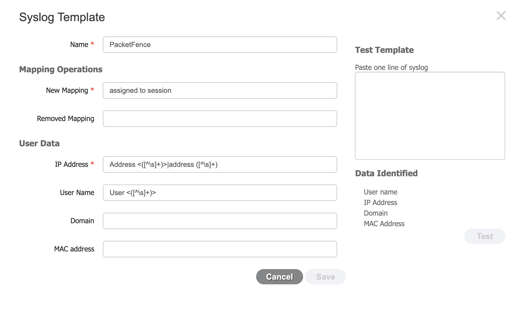
-
The new mapping should be set to:
assigned to session -
The regular expression for the IP address is:
Address <()>|address ([^\s]) -
The regular expression for the username is:
User <([^\s]+)>
19.3.3. Syslog provider
To add PacketFence as an identity provider, hover over "Providers" and click "Syslog Providers.", then click "Add".
Then add each of your PacketFence servers as Syslog providers using the syslog template you created above. In the case of a cluster, add each member management IP and the management virtual IP.
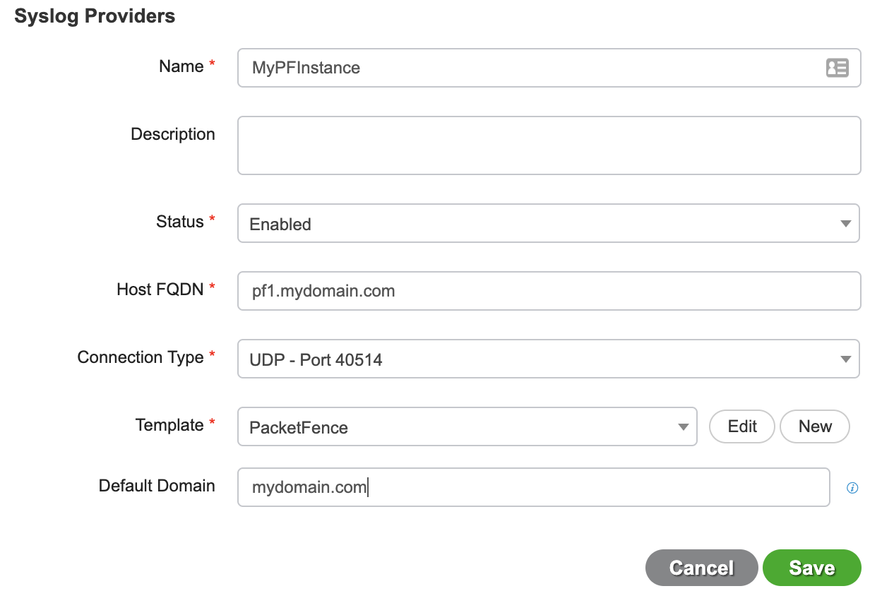
Make sure your syslog header configuration matches this:
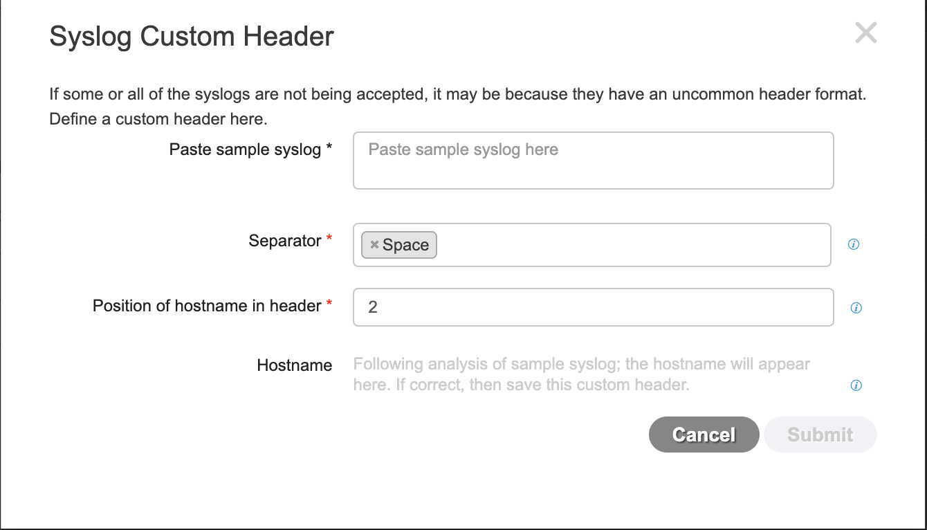
19.3.4. PacketFence configuration
Add a Cisco ISE-PIC firewall SSO entry in "Configuration→Integration→Firewall SSO"
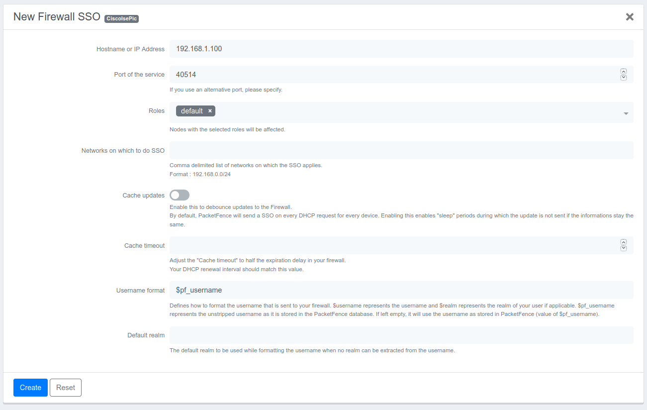
- Hostname or IP Address: IP of your Cisco ISE-PIC instance
- Port: 40514
- Roles: add the roles that you want to do SSO with
You should then see User Sessions populating under “Live Logs” in ISE-PIC. The source should say "syslog"
19.4. FortiGate
19.4.1. Configuration of the RSSO Agent
In FortiGate administration: User & Device → User → User Groups → Create New.
- Name: RSSO_group
- Type: RADIUS Single Sign-On (RSSO)
- RADIUS Attribute Value: RSSO_Student (use PacketFence rolename, case-sensitive)
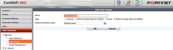
View at User & Device → Monitor → Firewall.
19.4.2. Configure the endpoint attribute
Default endpoint attribute is Calling-Station-Id (MAC address shows as User Name). Change via CLI:
config user radiusedit RSSO_agentset rsso-endpoint-attribute User-Nameend
19.4.3. Activate the Accounting Listening
Go to System → Network → Interfaces.
Select PacketFence communication interface, check 'Listen for RADIUS Accounting Messages', confirm.
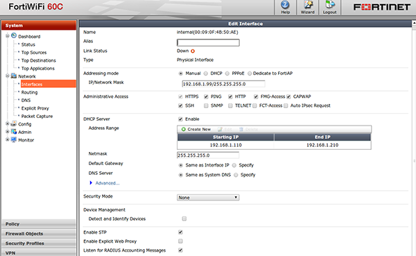
19.4.4. SSO Configuration in PacketFence
Go to Configuration → Integration → Firewall SSO → Add Firewall → FortiGate.
- Hostname or IP Address: IP of your firewall
- Secret or Key: secret (radius shared secret)
- Port: 1813
- Roles: add the roles that you want to do SSO
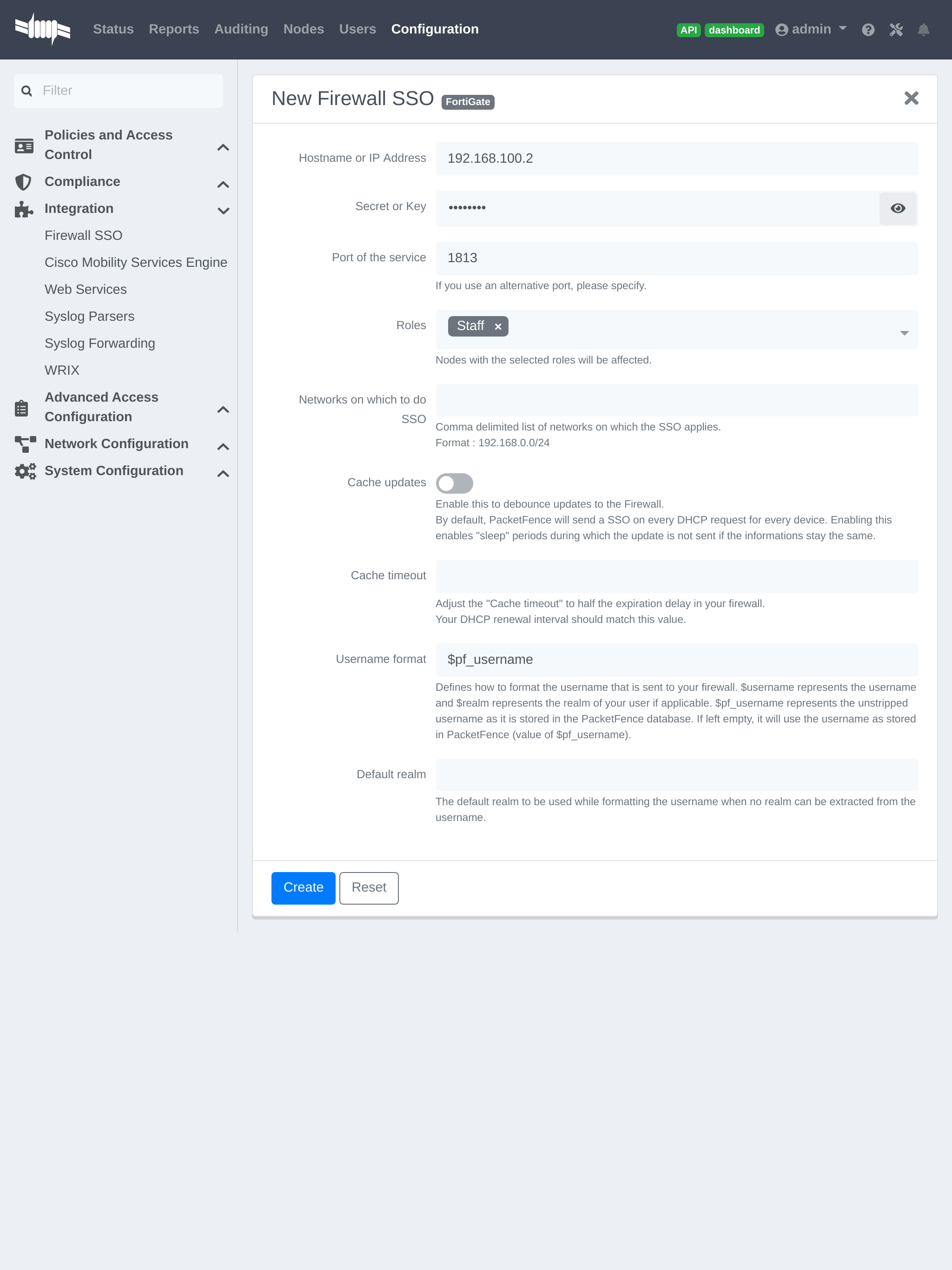
19.4.5. Verification
If you want to see if it’s working, you can log into the firewall over SSH and run these following commands:
di debug enabledi debug application radiusd -1
19.6. JSON-RPC
19.6.1. JSON-RPC interface
The JSONRPC module shipped with PacketFence is meant as a generic firewall SSO module to be used with Linux or BSD firewalls that do not by default ship with a vendor-specific interface to do SSO with.
A compatible server must implement the methods Start and Stop, both with the
identical set of parameters provided below.
- Protocol: JSON-RPC 2.0 over HTTPS
- Authentification: HTTP Basic authentication
-
Methods:
StartandStop -
Parameters:
-
user(string): Username that registered the device -
mac(string): MAC address of the device -
ip(string): IP address of the device -
role(string): PacketFence role assigned to the device -
timeout(int): Duration until the registration expires in seconds
-
-
Response: Success must be indicated by
"result": ["OK"]. Every string other thanOKis taken as an error message.
A simple JSON-RPC server written in Python that is compatible with this specification and creates ipsets based on the SSO information provided by PacketFence can be found at https://github.com/tribut/ipset-rpcd.
19.6.2. SSO Configuration in PacketFence
Go to 'Configuration' → 'Integration' → 'Firewall SSO' → 'Add Firewall' → 'JSONRPC'.
- Hostname or IP Address: IP of your JSON-RPC server
- Username and Password: HTTP Basic credentials
- Port of the service: 9090
- Roles: Add the roles that you want to do SSO with
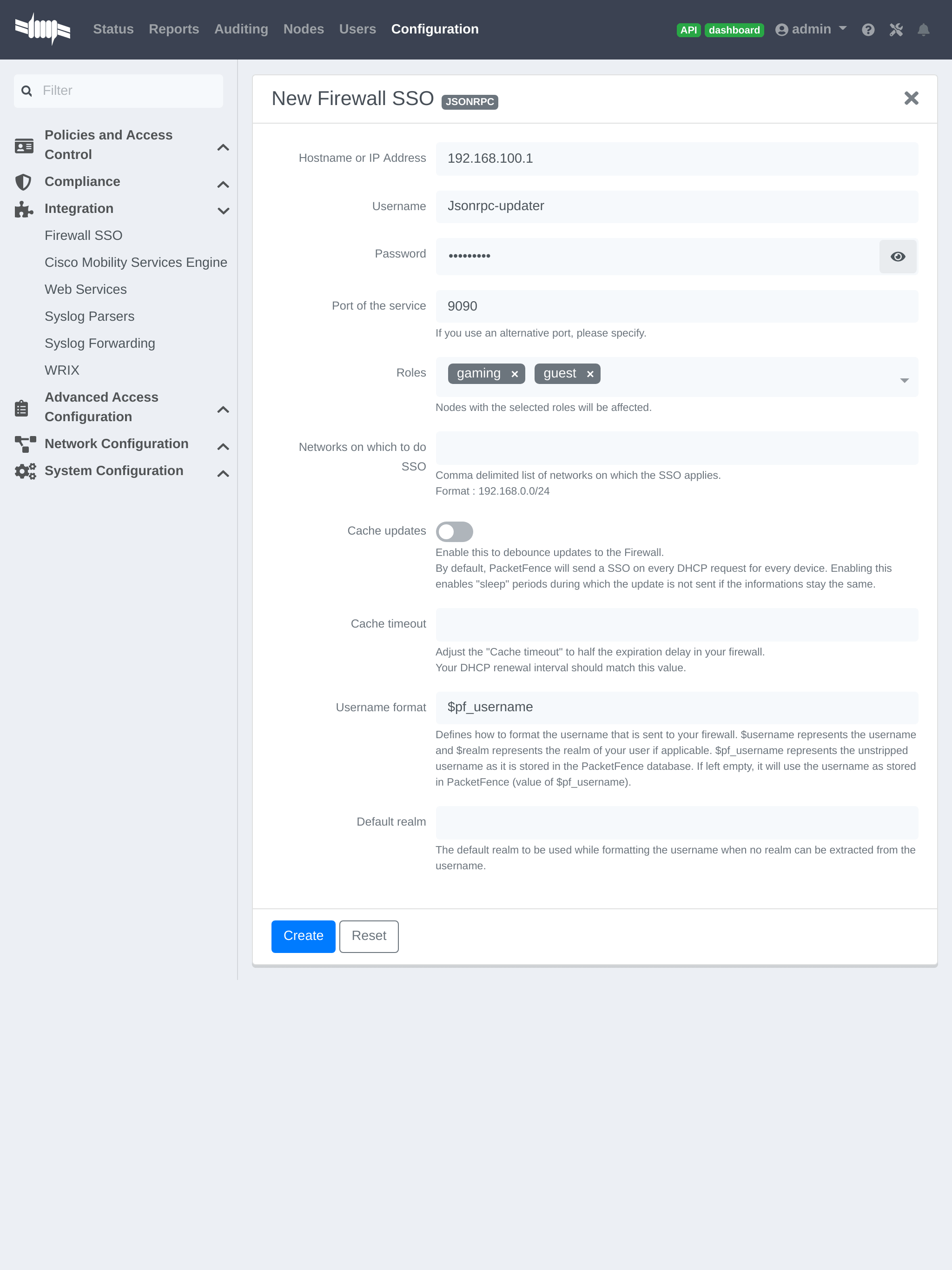
19.7. Juniper SRX
19.7.1. Configuration of the Juniper SRX in PacketFence
Go to Configuration → Integration → Firewall SSO → Add Firewall → JuniperSRX.
- Hostname or IP Address: IP of your JuniperSRX
- Firewall type: JuniperSRX (JuniperSRX = HTTPS requests)
- Password: secret
- Port: 8443
- Roles: add the roles that you want to do SSO
19.7.2. Step 1: webapi configuration
You need to setup webapi management as follows
set system services webapi user PFset system services webapi user password YOURPASSWORDset system services webapi client PF_MANAGEMENT_IP_ADDRESS
set system services webapi https port PORT_YOU_WANT_TO_USE i.e. 8443set system services webapi https default-certificate
Next setup user entry settings
set services user-identification authentication-source aruba-clearpass authentication-entry-timeout 120set services user-identification authentication-source aruba-clearpass no-user-queryset services user-identification device-information authentication-source network-access-controller
Then you need to allow traffic from the PacketFence management interface to port you set up on webapi settings (i.e. 8443) on SRX device.
19.7.3. Step 2: Verification
For debuging the webapi set (disable it when you won’t need it anymore):
set system services webapi debug-log api-logset system services webapi debug-level notice
To check registered device entries on SRX use
show services user-identification authentication-table authentication-source all ( extensive for more detailed informations)
or
run show services user-identification device-information table all extensive
to see more details about OS, device type etc.
19.8. Palo Alto
19.8.1. Installation using XMLAPI
Create a SSO role
Create SSO role on PaloAlto firewall web interface.
Go to Device → Admin Roles → Add.
Create role 'SSO_Role', under 'XML API' tab enable everything, validate with 'OK'.
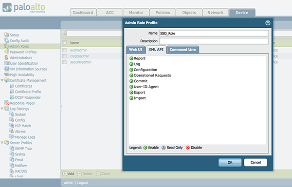
Create the account in PAN-OS
Associate user with created role.
Go to Device → Administrators → Add.
- Name: xmluser
- Authentication Profile: None
- Password: xmluser
- Role: Role Based
- Profile: SSO_Role (Previously created)
- Password Profile: None
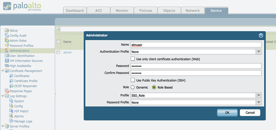
Get the XML Key
It should display:
<response status="success"><result><key>LUFRPT1jeFV6SHd1QnJHaU55dnYvRlFNSkJNeTR6Uzg9TDgzNVlj0=</key></result></response>
SSO Configuration in PacketFence
Now that we have the key, we will configure the PaloAlto firewall in PacketFence.
Go to Configuration → Integration → Firewall SSO → Add Firewall → PaloAlto.
- Hostname or IP Address: IP of your firewall
- Transport: HTTP
- Secret or Key: LUFRPT1jeFV6SHd1QnJHaU55dnYvRlFNSkJNeTR6Uzg9TDgzNVlj0= (use the key previously generated)
- Port of the service: 443
- Roles: add the roles that you want to do SSO with
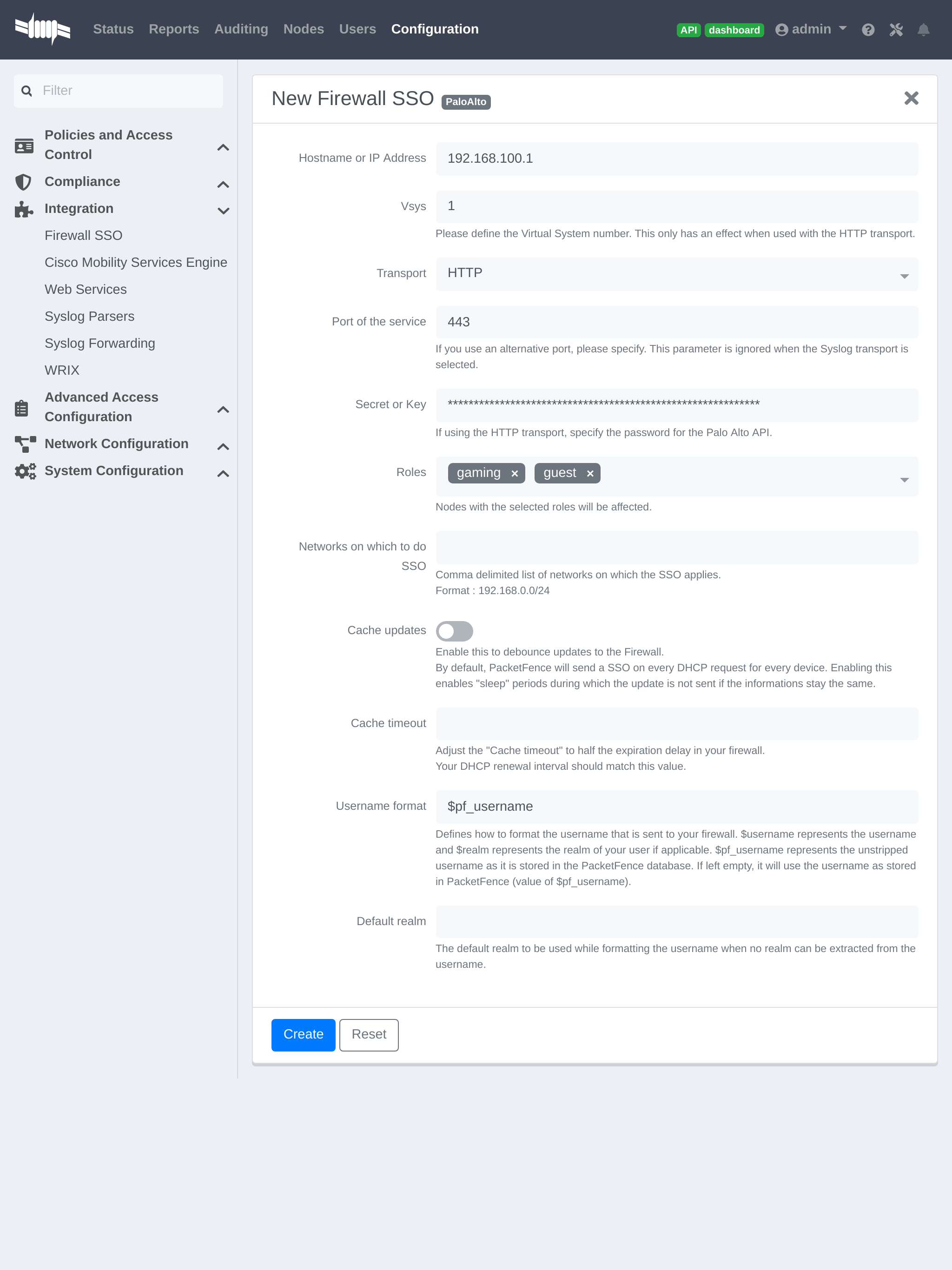
Verification
Now we will check that PacketFence is sending information when a user registers on the portal. If the process worked, you will see the entry in the PaloAlto database.
Use SSH on the PaloAlto firewall and run this command:
admin@PA-VM> show user ip-user-mapping allIP Vsys From User IdleTimeout(s) MaxTimeout(s)--------------- ------ ------- -------------------------------- -------------- -------------192.168.100.10 vsys1 XMLAPI domain\user1 Never Never
19.8.2. Installation using syslog
Create a filter
You will first need to create a filter to parse the SSO line that PacketFence will send. This can be done in 'User Identification→User Mapping'
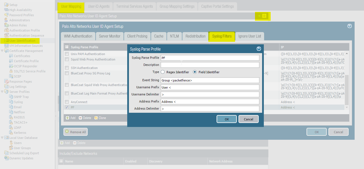
Assign the filter to a 'Monitored Server'
Next, configure the filter to be used in a syslog receiver on the Palo Alto. In order to do so, go in 'User Identification→User Mapping' and configure a syslog sender.
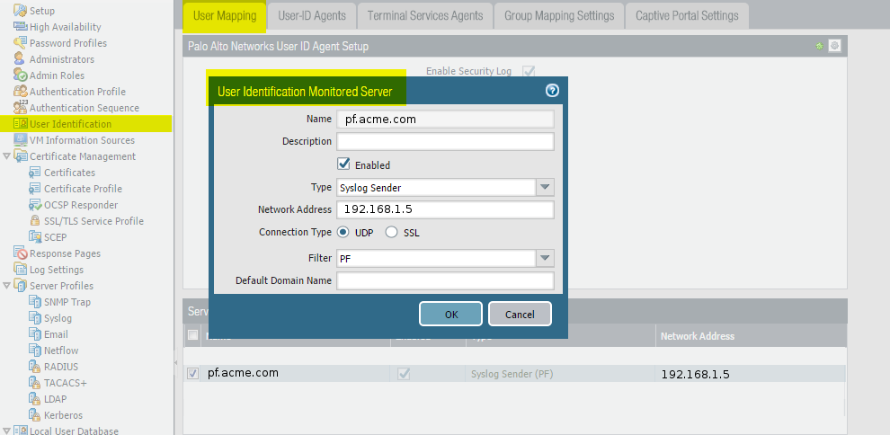
SSO Configuration in PacketFence
Next you need to configure the firewall in PacketFence.
Go to Configuration → Integration → Firewall SSO → Add Firewall → PaloAlto.
- Hostname or IP Address: IP of your firewall
- Transport: Syslog
- Secret or Key: Ignore this parameter
- Port of the service: Ignore this parameter
- Roles: add the roles that you want to do SSO with
Verification
Now we will check that PacketFence is sending information when a user registers on the portal. If the process worked, you will see the entry in the PaloAlto database.
Use SSH on the PaloAlto firewall and run this command:
admin@PA-VM> show user ip-user-mapping allIP Vsys From User IdleTimeout(s) MaxTimeout(s)--------------- ------ ------- -------------------------------- -------------- -------------192.168.100.10 vsys1 syslog domain\user1 Never Never
Usage:
Socket::inet_ntoa(ip_address_sv)
, check that the hostname of your PacketFence
server can be resolved correctly on the server itself. If its not, make sure you
adjust your hosts file or your DNS server.19.9. Troubleshooting SSO Integration
For SSO integration issues, verify firewall API connectivity and check integration logs as described in Log Files and Network Connectivity Issues in the Troubleshooting section.
20. Performing Compliance Checks
PacketFence supports either Nessus and OpenVAS as a scanning engine for compliance checks. Since PacketFence v5.1 it is possible to create multiple scan engine configurations and assign them on specific captive portals. It means for example that it is now possible to activate a scan for specific Operating System only on a specific SSID.
20.1. Installation
20.1.1. Nessus
Please visit https://www.tenable.com/downloads/nessus to download Nessus v7 and install the Nessus package for the operating system. Also register for the HomeFeed (or the ProfessionalFeed) in order to get the plugins.
After installing Nessus, follow the Nessus documentation for the configuration of the Nessus Server, and to create a user for PacketFence.
20.1.2. OpenVAS
Requirements
First install OpenVAS along with XYZ and ABC in order to manage
OpenVAS remotely via the omp command line.
In order to validate proper connectivity from PacketFence to OpenVAS for remote management, execute the following command (replacing admin by the user to use for PacketFence to communicate with OpenVAS):
# omp -u admin -p 9390 -X "<get_version/>"
The output of the above command should provide the version of OpenVAS.
Otherwise, ensure all the necessary components are in place for management
through the omp command line client and that PacketFence is able to
communicate with OpenVAS on port 9390.
Configuring the alert
Configure an alert policy in OpenVAS to inform PacketFence of the completion of a task. The httpd.portal daemon takes care of handling this callback so ensure that "portal" is in the additional listening daemons on the management interface in PacketFence.
In order to create the alert policy, go in the Greenbone Security Assistant, then in "Configuration → Alerts" and create a new alert with the following configuration
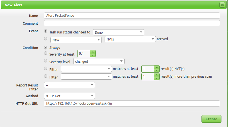
Where:
- Name is of the value chosen
- Ensure the event is set to "Task run status changed to: Done"
- Ensure the condition is set to "Always"
- Method is set to "HTTP Get"
-
HTTP Get URL is set to: http://PF_MANAGEMENT_IP/hook/openvas?task=$n
- In the URL above, only change PF_MANAGEMENT_IP to the management IP of the PacketFence server. Leave the rest of the URL untouched as this exact URL and format is expected by PacketFence.
Collecting the identifiers
Once connectivity is working between PacketFence and OpenVAS, use the Greebone Security Assistant to obtain the following information for configuring PacketFence
Alert ID
Navigate to Configuration → Alerts, then click on the alert configured above to view it, and note down the ID of the alert.
Scan config ID
Navigate to Configuration → Scan Configs and then select the scan configuration to use to scan the hosts. In this scan config view, note down the ID.
Report format ID
Navigate to Configuration → Report Formats and then select the CSV Results
report format. In this view, note down the ID.
20.2. Configuration
In order for the compliance checks to correctly work with PacketFence (communication and generate security events inside PacketFence), configure these sections:
20.2.1. Scanner Definition
First go in Configuration and Scanner Definition: Configuration → Compliance → Scan Engines
Then add a New Scan Engine
There are common parameters for each scan engines:
Name: the name of the scan engineRoles: Only devices with these role(s) will be affected (Optional)OS: Only devices with this Operating System will be affected (Optional)Duration: Approximate duration of scan (Progress bar on the captive portal)Scan before registration: Trigger the scan when the device appear on theregistration vlanScan on registration: Trigger the scan just after registration on the captiveportalScan after registration: Trigger the scan on the production network(pfdhcplistener must receive production dhcp traffic)
Specific to Nessus:
Hostname or IP Address: Hostname or IP Address where Nessus is runningUsername: Username to connect to Nessus scanPassword: Password to connect to Nessus scanPort of the service: port to connect (default 8834)Nessus client policy: the name of the policy to use for the scan (Must bedefined on the Nessus server)
Specific to OpenVAS:
Hostname or IP Address: Hostname or IP Address where OpenVAS is runningUsername: Username to connect to OpenVAS scanPassword: Password to connect to OpenVAS scanPort of the service: port to connect (default 9390)Alert ID: the ID of the alert configuration on the OpenVAS serverScan config ID: the ID of the scanning configuration on the OpenVAS serverReport format ID: the ID of the report format for the "CSV Results"
Rules syntax
The syntax of the rules are simple to understand and use same syntax as VLAN filters.
- Request is the SQL request to launch on the remote device, must know what the request will return to write the test.
Inside the Rules Actions field we define 2 sorts of blocs:
-
The test bloc (i.e.
[explorer]) -
The action bloc (i.e.
[1:explorer])
The test bloc is a simple test based on the result of the request:
- attribute is the attribute to test
-
operator can be:
- is
- is_not
- match
- match_not
- advance
- value is the value to compare
Multiple test blocs can be defined.
The action bloc is where the logic will be defined. All actions available are
identical to VLAN filters. Take a look at
/usr/local/pf/conf/vlan_filters.conf.example for all available
actions.
20.2.2. Security Events Definition
Create a new security event section and specify:
Using Nessus:
trigger=Nessus::<security event ID>
Using OpenVAS:
trigger=OpenVAS::<security event ID>
Where security event ID is either the ID of the Nessus plugin or the OID of
the OpenVAS plugin to check for. Once the configuration is finished,
reload the security event related database contents using:
pfcmd reload security_events
20.2.3. Assign Scan definition to connection profiles
The last step is to assign one or more scanner configured to one or more connection profiles. Go in Configuration → Policies and Access Control → Connection Profiles → Edit a Profile → Add Scan
Hosting Nessus / OpenVAS remotely
Because of the CPU intensive nature of an automated vulnerability assessment, we recommend that it is hosted on a separate server for large environments. To do so, a couple of things are required:
- PacketFence needs to be able to communicate to the server on the port specified by the vulnerability engine used
- The scanning server need to be able to access the targets. In other words, registration VLAN access is required if scan on registration is enabled.
If using the OpenVAS scanning engine:
- The scanning server need to be able to reach PacketFence’s Admin interface (on port 1443 by default) by its DNS entry. Otherwise PacketFence won’t be notified of completed scans.
- A valid SSL certificate must be on the PacketFence server
If using the Nessus scanning engine:
- Just change the host value to the Nessus server IP.
20.3. Rapid7 integration
PacketFence supports integration with Rapid7 to start scans automatically when a device connects to the network and also to receive the Rapid7 alerts via syslog.
20.3.1. Rapid7 installation
- Install the InsightVM application
- Run the application
- Logon to the server: https://'YourRapid7ServerIP:3780
20.3.2. Configuring the scan engine
Rapid7 PacketFence user
First, create credentials for PacketFence so that it can perform API calls on Rapid7. In order to do so, on Rapid7, go in Administration → Users and click on Create. Then configure the appropriate username and password and make sure the account is enabled.
Next, in the roles of that user, select the "Custom" role and assign at least the following privileges to the new user:
- Manage Sites
- Manage Scan Enginespfcron
- View Site Asset Data
- Specify Scan Targets
- View Group Asset Data
Next, in "Site access" and "Asset group access", ensure to provide access to this user to all the assets and sites it needs to manage. When in doubt, grant access to all sites and asset groups.
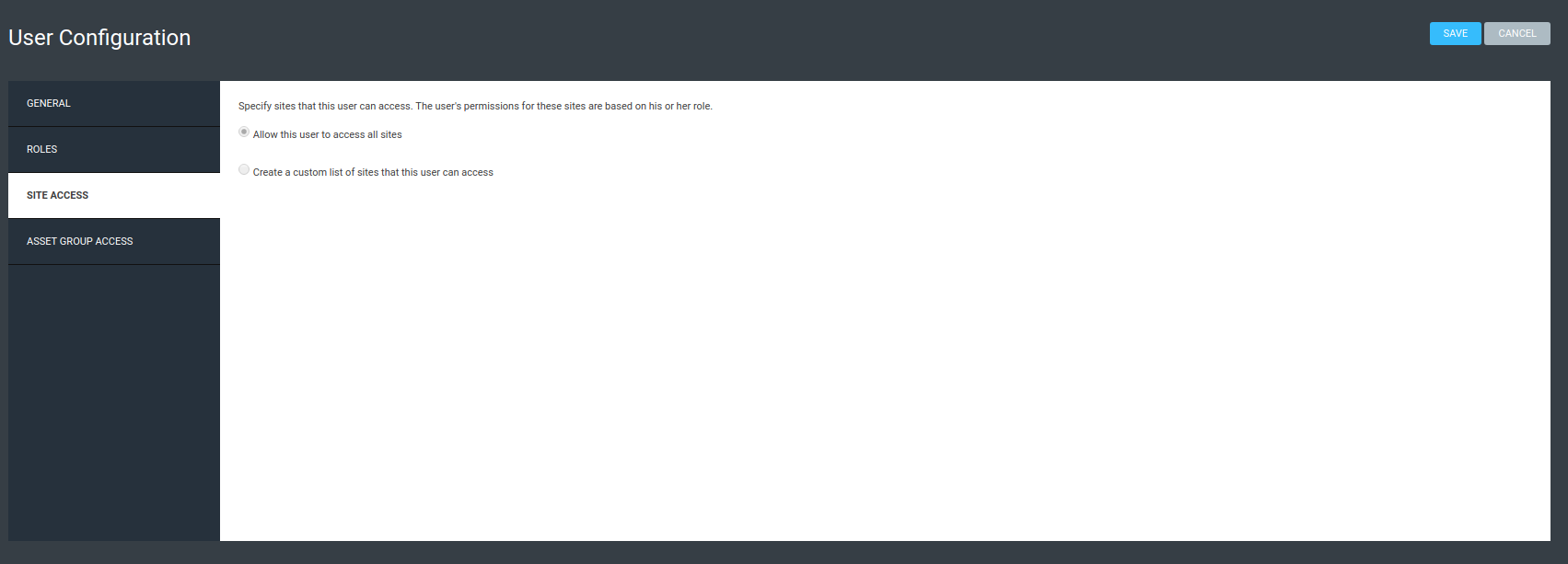
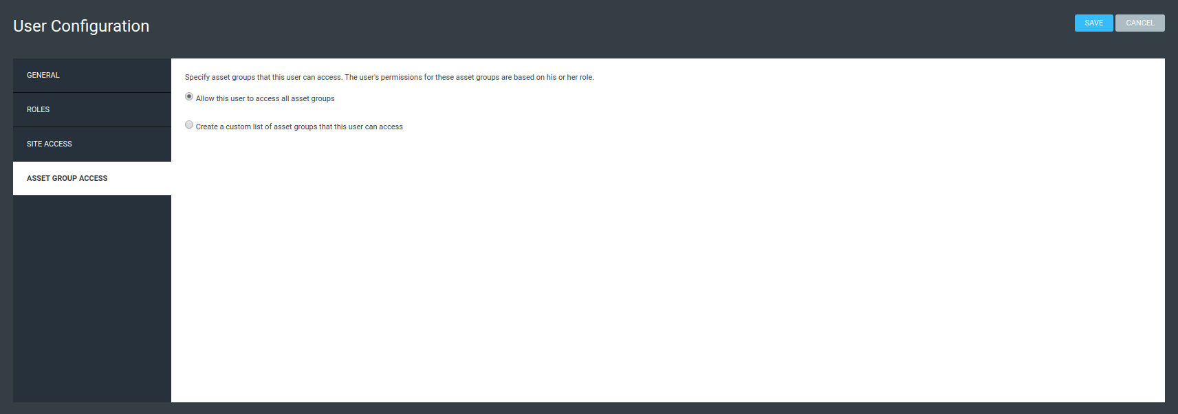
Configure the scan engine in PacketFence
Once the user is created, create the scan engine by going in Configuration → Compliance → Scan Engines and creating a New Scan Engine of the type Rapid7
Notes on the configuration:
- 172.20.20.230 is the IP address (hostname can also be configured) of the Rapid7 server
- Verify Hostname must be disabled unless a valid SSL certificate is configured for the configured Rapid7 hostname
- Roles and OS represents the roles and operating systems for which to apply this scan engine. Leaving them empty will apply the policy to all devices.
- Scan before/on/after registration controls when the automated scans are started for the devices PacketFence sees. To only start the scans manually, leave those unchecked.
- It will not be possible to select a scan template, site and scan engine when initially configuring the engine. First configure the access and credentials and edit the engine again to be able to select those from the available values in Rapid7.
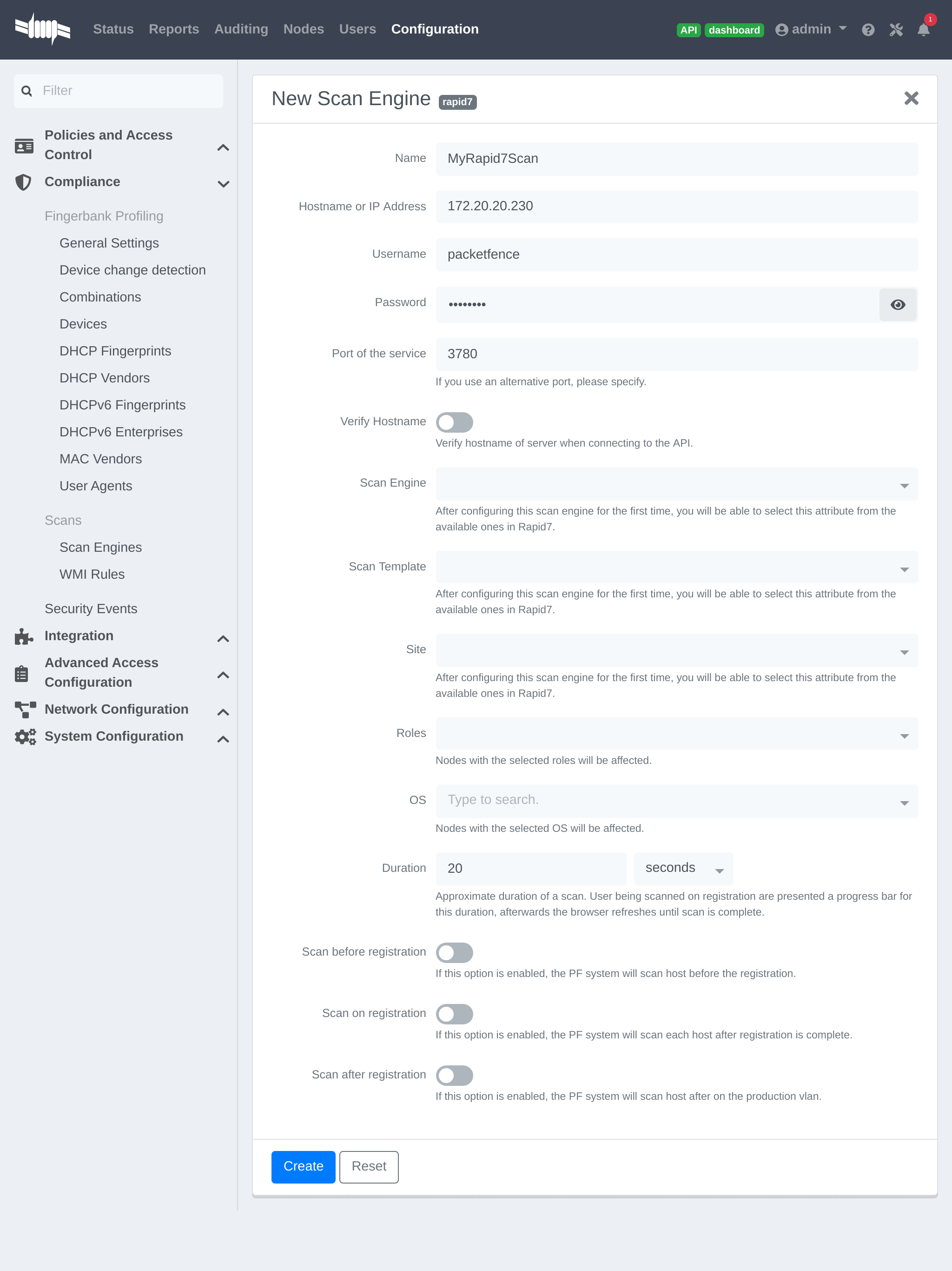
Assign the engine to a connection profile
With the scan engine now created, assign it to the connection profile that the endpoints use. In order to do so, go in Configuration → Connection Profiles, select the connection profile and add the scan engine there.
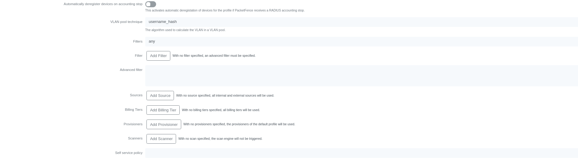
Viewing data on endpoints
With the scan engine integration completed, PacketFence will now automatically start scans on the endpoints it sees DHCP for and it will be possible to view the Rapid7 information of the endpoints by going in the Nodes tab in PacketFence and then viewing a node and browsing its Rapid7 tab.
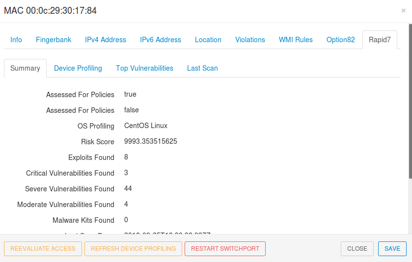
20.3.3. Configuring the syslog integration
PacketFence also supports integration with the syslog forwarding of Rapid7 (with or without the scan engine integration) in order to receive vulnerability alerts from Rapid7.
Sending syslog information to PacketFence
In Rapid7:
- First select the site to have alerts for and click on Manage Site
- In the site management tabs select Alerts, then create a new alert
Enable: Must be checked. Alert Name: Rsyslog to PacketFence or else. Maximum Alerts to send: blank (none) Scan events: Check all. Vulnerability Events: Any severity ; Check as well Confirmed, Unconfirmed, Potential Notification Method: Select Syslog message Syslog Server: PacketFence cluster VIP or server IP for a standalone
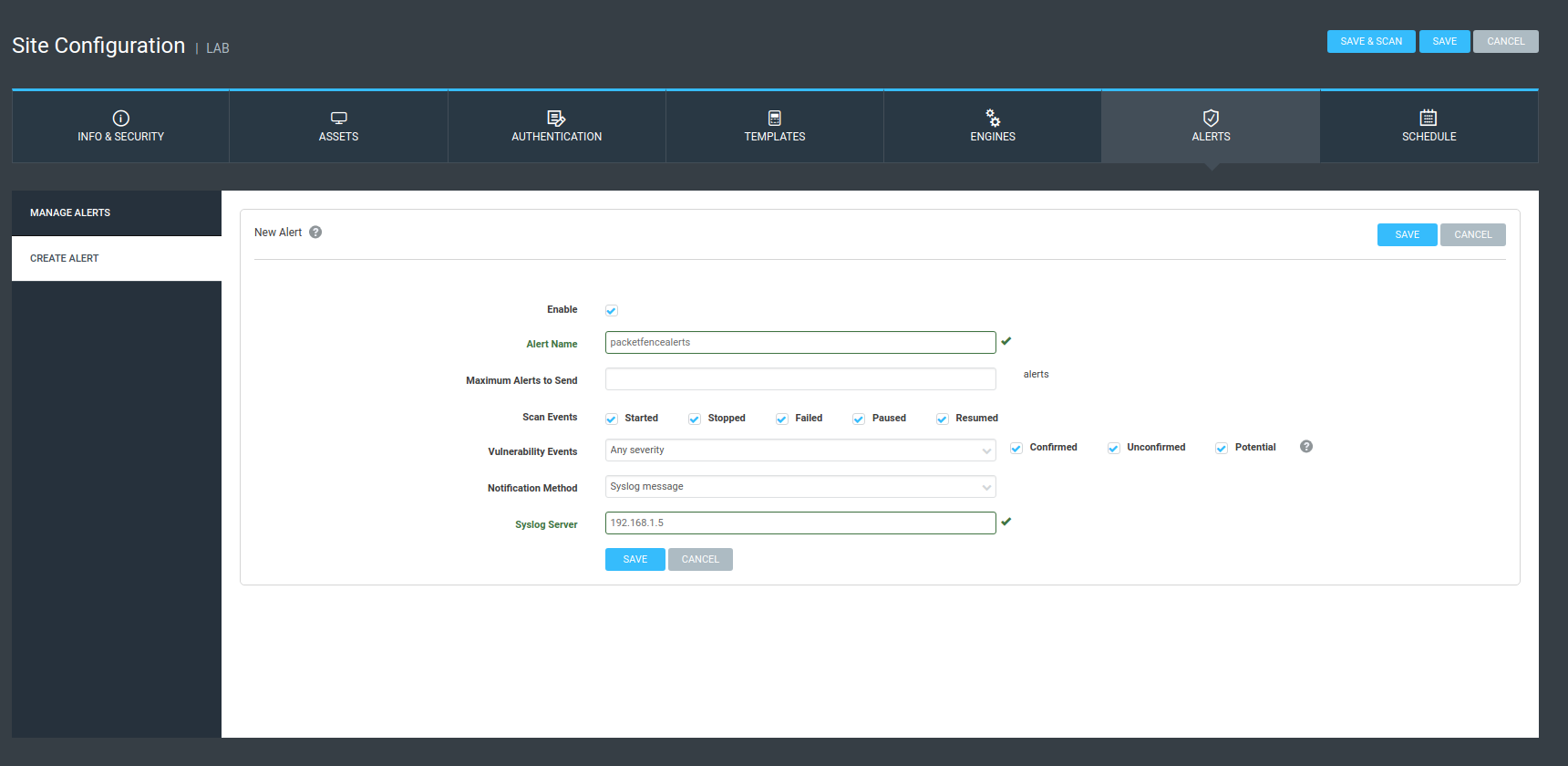
Creating the alert pipe on PacketFence
First, logon to PacketFence Server with a ssh terminal, then create the fifo pipe file that PacketFence will use to get data from Rapid7.
mkfifo /usr/local/pf/var/run/nexpose_pipe
Create a new file named /etc/rsyslog.d/nexpose-log.conf with the following content
# rsyslog conf for Rapid7 Nexpose server logs receptionif $programname == 'Nexpose' then /usr/local/pf/var/run/nexpose_pipe& ~
Next, modify /etc/rsyslog.conf to accept syslogs data on 'udp 514' by uncommenting the following two lines:
$ModLoad imudp$UDPServerRun 514
Restart the 'rsyslog' service
service rsyslog restart
At this point PacketFence must be able to get the Rapid7 audit results via syslog.
tcpdump -i any dst host PACKETFENCE_SERVER_IP on the Rapid7 Nexpose server and tcpdump -i any src host RAPID7_IP on the PacketFence server.Creating the event handler
In the PacketFence admin interface, go to Configuration → Integration → Event Handlers and add a new Nexpose event handler
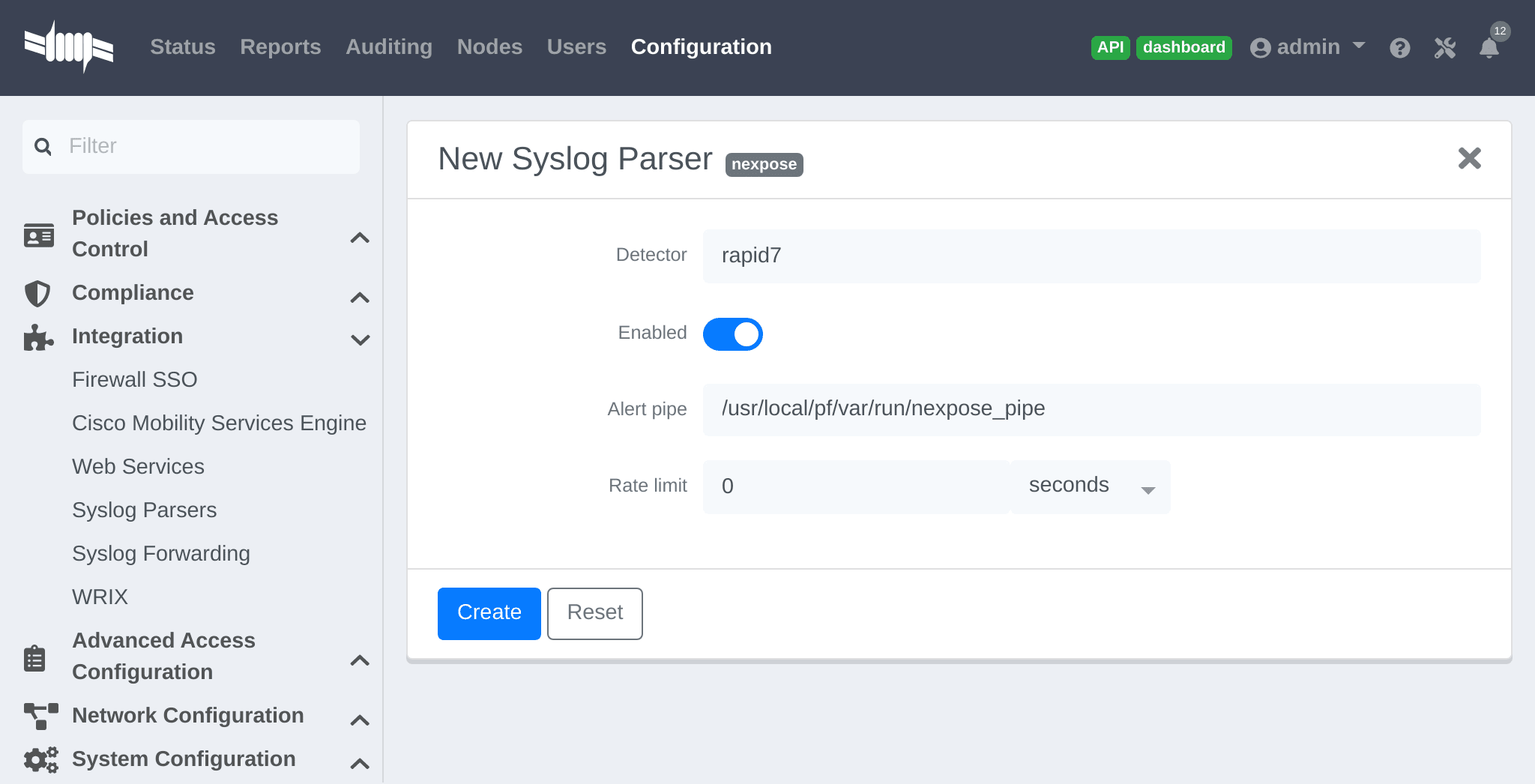
- As Detector, put the name chosen for this parser.
-
In Alert pipe, put the 'absolute' path to our nexpose pipe (
/usr/local/pf/var/run/nexpose_pipeif the same name as above was used)
Once done, restart the following services
/usr/local/pf/pfcmd service pfdetect restart/usr/local/pf/pfcmd service pfqueue restart
Now that PacketFence is properly configured to receive information from Nexpose, we can configure it to perform some actions on the alerts it receives. In the PacketFence admin interface, go to Configuration → Compliance → Security Events and create a new security event.
Make sure to set the following parameters in the 'Definition' tab:
- Enable: Set it to ON
- Action: This is where to put what PacketFence should do, refer to the security events documentation in this guide for details on these.
Next, in the 'Triggers' tab:
- Click on the plus (+), on the right side of the page.
- On the second line, choose the appropriate trigger between "nexpose_event_contains" or "nexpose_event_start_with"
- Choose "nexpose_event_contains" if knowing, for example, the "Common Vulnerabilities and Exposures" to take action on.
- For "nexpose_event_contains": Put there the CVE or the vulnerability name to look for.
- For "nexpose_event_start_with": Put there the full vulnerability name that can be found in the Nexpose report, on the Nexpose GUI
- Click on ADD, then SAVE
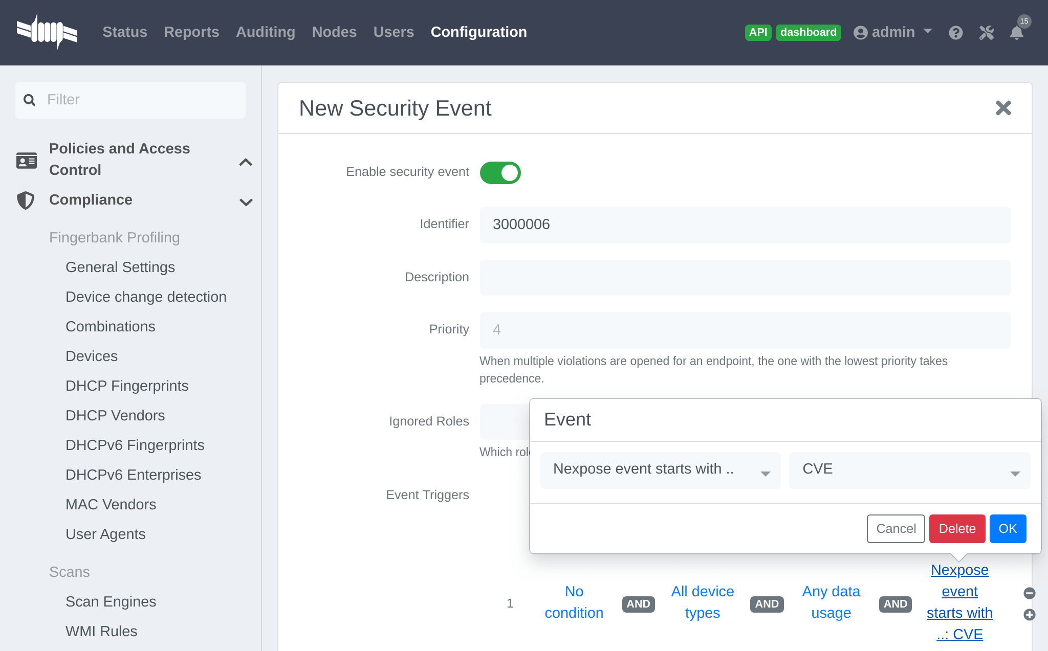
For more info on security event actions, go to the Blocking malicious activities with security events section of this guide.
21. Integrating Provisioning Agents
21.1. PacketFence Apple, Android and Windows Wireless Provisioning
Provisioners enable automatic device configuration for proper SSID connection, authentication method (e.g., EAP-TLS), and CA certificate trust.
Apple devices (iPhones, iPads, iPods, Mac OS X 10.7+) support wireless profile importation via mobileconfig XML format. Android supports this through Android PacketFence Agent profile import. Installing files automatically configures wireless settings for given SSID, simplifying manual configuration for hidden SSIDs. PacketFence generates profiles per administrator preferences, pre-populating user credentials (excluding password). Users install generated file to use new SSID.
Windows agent imports and applies provisioned profile; users only enter username and password.
21.1.1. Configure the feature
Configure SSID for devices after authentication.
In administration interface: Configuration → Advanced Access Configuration →
Provisioners. Select 'android'/'ios'/'Windows' provisioner. Enter SSID
information and applicable roles. Repeat for desired provisioners. Default
RADIUS certificate path: /usr/local/pf/raddb/certs/server.crt.
Add 'Android', 'iOS' and 'Windows' provisioners to 'Connection Profile' configuration. If no profile defined, configure 'default' connection profile with created provisioners.
Add provisioner for other device classes: click Add Provisioner, complete form
with different Provisioning ID per provisioner.
- Roles: Defines affected devices; if empty, affects all devices for this class.
- SSID: Defines SSID configured on device using authentication profile.
- EAP-Type: Authentication method; set to EAP-TLS for PacketFence PKI integration.
- Security type: Set to WPA2-Enterprise for PacketFence PKI integration.
- PKI Provider: Must match provider configured in PKI provider section.
Configure provisioning SSID (e.g., OnBoarding-PF) open with MAC Authentication
pointing to PacketFence. Create New Portal Profile, add filter SSID with
SSID name, add authentication source and provisioners. Logged-in users follow
captive portal instructions to receive certificates.
Android specifications
For Android provisioning support, you must activate and adjust the passthroughs. You might need to adapt them depending on your geolocality.
In the administation inferface, go in Configuration → Network Configuration → Networks → Fencing. Activate 'Passthrough' and make sure the following passthroughs domains are present:
*.ggpht.com,*.googleusercontent.com,android.clients.google.com,*.googleapis.com,*.android.clients.google.com,*.gvt1.com,*.l.google.com,play.google.com,*.gstatic.com
Then run the following commands so that passthroughs become effective:
/usr/local/pf/bin/pfcmd configreload hard/usr/local/pf/bin/pfcmd service pfdns restart
Next, make sure you are using a valid SSL certificate on your captive portal since Android devices will only be able to be provisioned on a captive portal that uses valid HTTPS
iOS specifications
Mac OS X/iOS require the provisioning profile to be signed if you want to remove
the untrusted warning when installing the profile. For more information,
please refer to the PKI guides referred earlier in 'Configure the feature'
above.
Other Corporate Devices
Let’s say that you now need to add some 'Linux computers' as 'corporate' devices.
Those devices cannot be authenticated via Machine Authentication, so we will need to use EAP-TLS and provide those devices with a certificate.
First of all make sure that your RADIUS certificate from the PacketFence server and the certificates that you will be provided are delivered from the same CA, else your authentication will not work. To enable EAP-TLS you will need to reconfigure the new RADIUS server certificate in the file conf/radiusd/eap.conf.
While creating the RADIUS server certifcate make sure to have the Extended key usage: servAuth.
Under the section tls-config tls-common, search for `private_key_file',
`certificate_file' and `ca_file'. Those should contain respectively the path of:
- the private key for your PacketFence server,
- the server certificate issued by your CA for your PacketFence server,
- the public key of your CA.
If you have an OCSP capable PKI you can configure it in the section OCSP in
the eap.conf file.
Lastely you will need to restart RADIUS to ensure the use of the new configuration and certificates. Please do the following:
/usr/local/pf/bin/pfcmd configreload hard/usr/local/pf/bin/pfcmd service radiusd restart
Make sure everything happens without errors.
Now that your RADIUS is ready to handle EAP-TLS, configure your SSID connection
profile on the corporate device using this method. Generate a client
certificate for your device and install it on.
Please configure an EAPTLS source which can be found while adding a new sources
under Configuration → Policies and Access Control → Authentication Sources
New internal Source → EAPTLS, simply give it a name, a description and a
catch-all rule. This will allow you to validate the authentication via EAP-TLS.
You can now create a new Portal Profile for EAP-TLS. Under the tab
configuration, section Configuration → Policies and Access Control →
Connection Profiles, New Connexion Profile and select as a filter the Sub
Connection Type as EAP-TLS, add your source EAP-TLS. Check the box
"Automatically register devices".
You now have a full flow working for your corporate devices.
The following is an example on how to configure an EAP-TLS connection for Windows/Android/Mac OS X/iOS
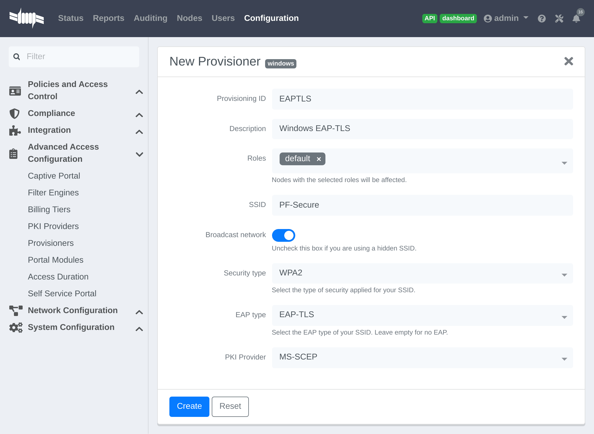
Mac OS X/iOS require the provisioning profile to be signed if you want to remove
the untrusted warning when installing the profile. You need to sign it with a
Certification Authority already trusted by the device such as e.g. VeriSign.
Configuring this has to be done in the 'Signing' tab in the "Apple devices".
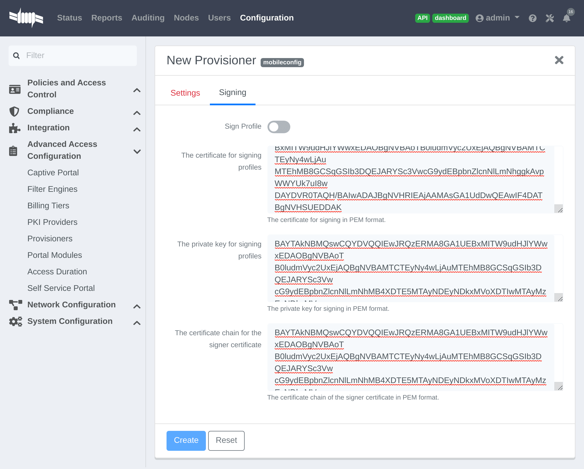
21.1.2. Profile generation
Upon registration, instead of showing the default release page, the user will be showing another version of the page saying that the wireless profile has been generated with a clickable link on it. To install the profile, Apple user owner simply need to click on that link, and follow the instructions on their device. Android user owner simply click to the link and will be forwarded to Google Play to install PacketFence agent. Simply launch the application and click to configure will create the secure SSID profile. It is that simple.
21.2. MobileIron
21.2.1. Configure MobileIron
First of all you will need to configure the basic functionality of MobileIron using their documentation.
MDM profile
One important step is to enable the MDM profile like in this screenshot. Note that this will require you to create an MDM certificate with Apple. Refer to the MobileIron documentation for specifics about this step.
21.2.2. Create an API user
Next, we will need a user that has the rights to access the MobileIron API in order to verify the state of the devices directly from PacketFence.
First go in the 'USERS & DEVICES' tab and then in 'Users' and click 'Add local user'.
Now enter the information about your user and note the user ID and password for usage in the PacketFence configuration, then hit 'Save'.
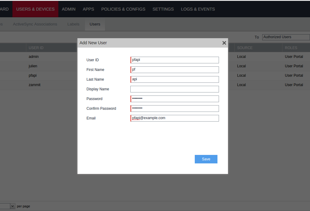
Now go in the 'ADMIN' tab, check the box next to your newly created user and then in 'Actions' select 'Assign to Space'.
Select the Global space at the top and then check API at the bottom. You should now see API in the roles list of your newly created user when viewing the users list.
21.2.3. Gather the boarding host
To find the boarding host, add a fake device to MobileIron and at the end of the process you will see the registration instructions.
In it you will find the boarding host and port for the PacketFence
configuration. In this case, the boarding host is m.mobileiron.net and the
boarding port is 50291.
21.2.4. Configure PacketFence
In PacketFence, MDM are referred to as provisioners. This will walk you through adding MobileIron as a provisioner.
Create the provisioner
Login to the admin interface, then go to Configuration → Advanced Access Configuration → Provisioners. Click 'Add provisioner' then select 'mobileiron'.
Now configure this new provisioner with the information you got above.
- The Provisioning ID is the friendly name of the provisioner.
- The Username is the user you created with API access above.
- The password is the password of the API user.
-
The host is the domain name of the instance + your account name if you have a cloud account (ex:
m.mobileiron.net/accountName) - Now add the download URI for the agent. See below for more details.
- The Boarding host is the host that you got in step 3.
- The Boarding port is the port that you got in step 3.
Here are the URIs that should work by default.
Replace accountName by your real account/instance name at MobileIron.
Add the provisioner to the connection profile
In order for the provisioner to be used by your captive portal you need to add it in its configuration. Go in 'Connection Profiles', then select the portal you want to modify and add 'mobileiron' as a provisioner.
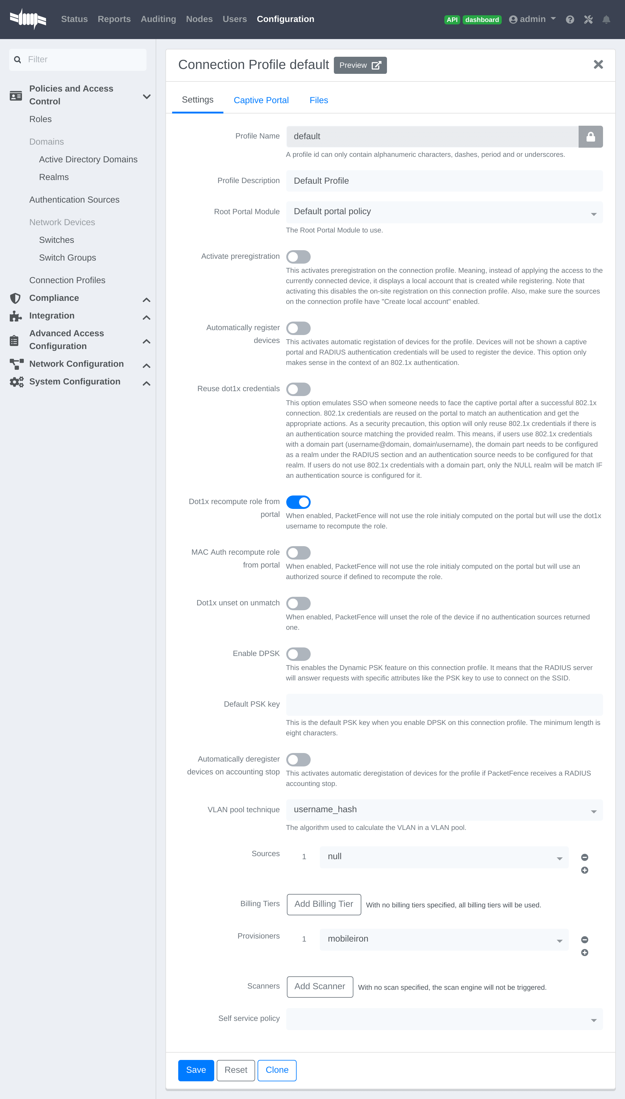
21.2.5. Add the necessary passthroughs
Next, still in the PacketFence administration console, go in 'Fencing' in the left menu, then scroll then to 'Passthroughs'.
Check the 'Passthrough' box above the field and add the following domains to the passthrough list.
- m.mobileiron.net
- *.itunes.apple.com
- itunes.apple.com
- play.google.com
- *.play.google.com
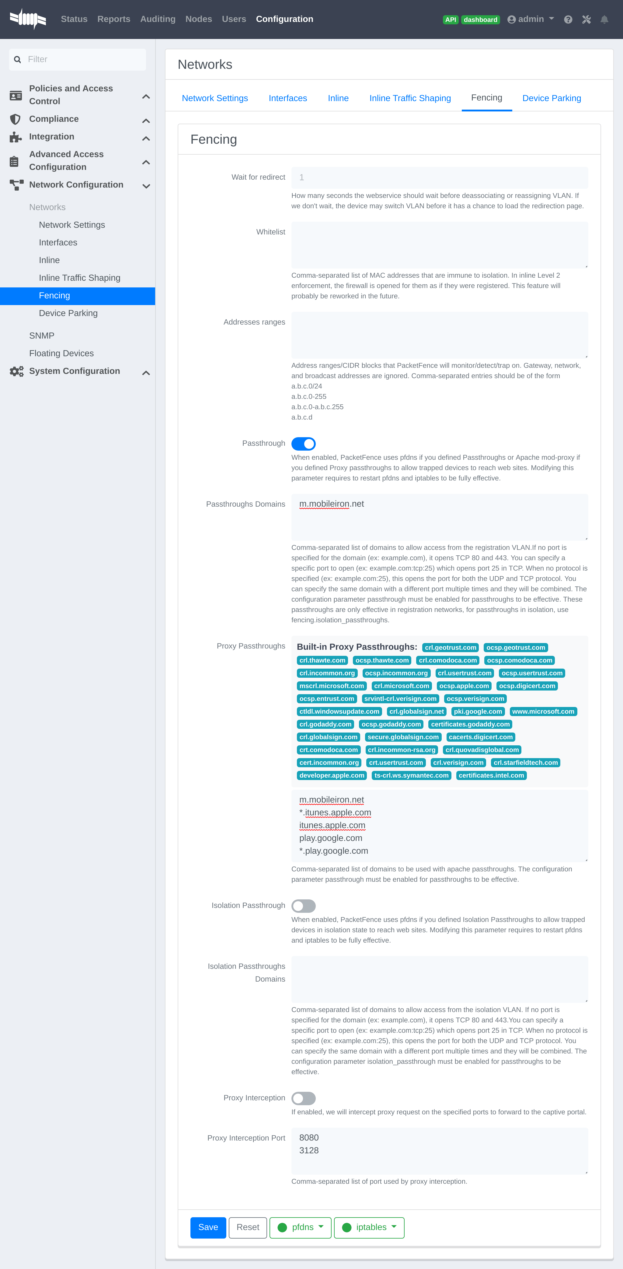
Restart PacketFence
Then run the following commands so that passthroughs become effective:
/usr/local/pf/bin/pfcmd configreload hard/usr/local/pf/bin/pfcmd service pfdns restart
21.2.6. Testing
You can now test that MobileIron is mandatory after the device registration. Connect a device to your test network and register like you normally would. At the end of the registration process you will be presented a page asking you to install the MobileIron on your device. After you install the agent click 'Continue'. If your access is enabled than this means the connectivity between PacketFence and MobileIron is good.
21.3. SentinelOne
21.3.1. Download the agents
You will first need to download the SentinelOne agents in order to host them on the PacketFence server.
In order to do so, in your SentinelOne management console, go in
'Settings→Updates', then download the Windows and Mac OSX agents on your
computer. Once they have been download transfer them on your PacketFence server
using SCP. This example will use /usr/local/pf/html/common/SentinelOne.exe as
the Windows agent path and /usr/local/pf/html/common/SentinelOne.pkg as the
Mac OSX agent path.
/usr/local/pf/html/common/ are accessible to users that are
on the captive portal. Make sure you put the agents file there or in another
user-accessible location.21.3.2. Create an API user
PacketFence will need a user on your SentinelOne instance in order to access the SentinelOne API. To create it, go in 'Settings→Users' and create a new user. Make sure, you note the password you put here for configuration in PacketFence.
21.3.3. Configure PacketFence
Create a new provisioner
Login to the admin interface, then go to Configuration → Advanced Access
Configuration → Provisioners.
Click 'Add provisioner' then select SentinelOne.
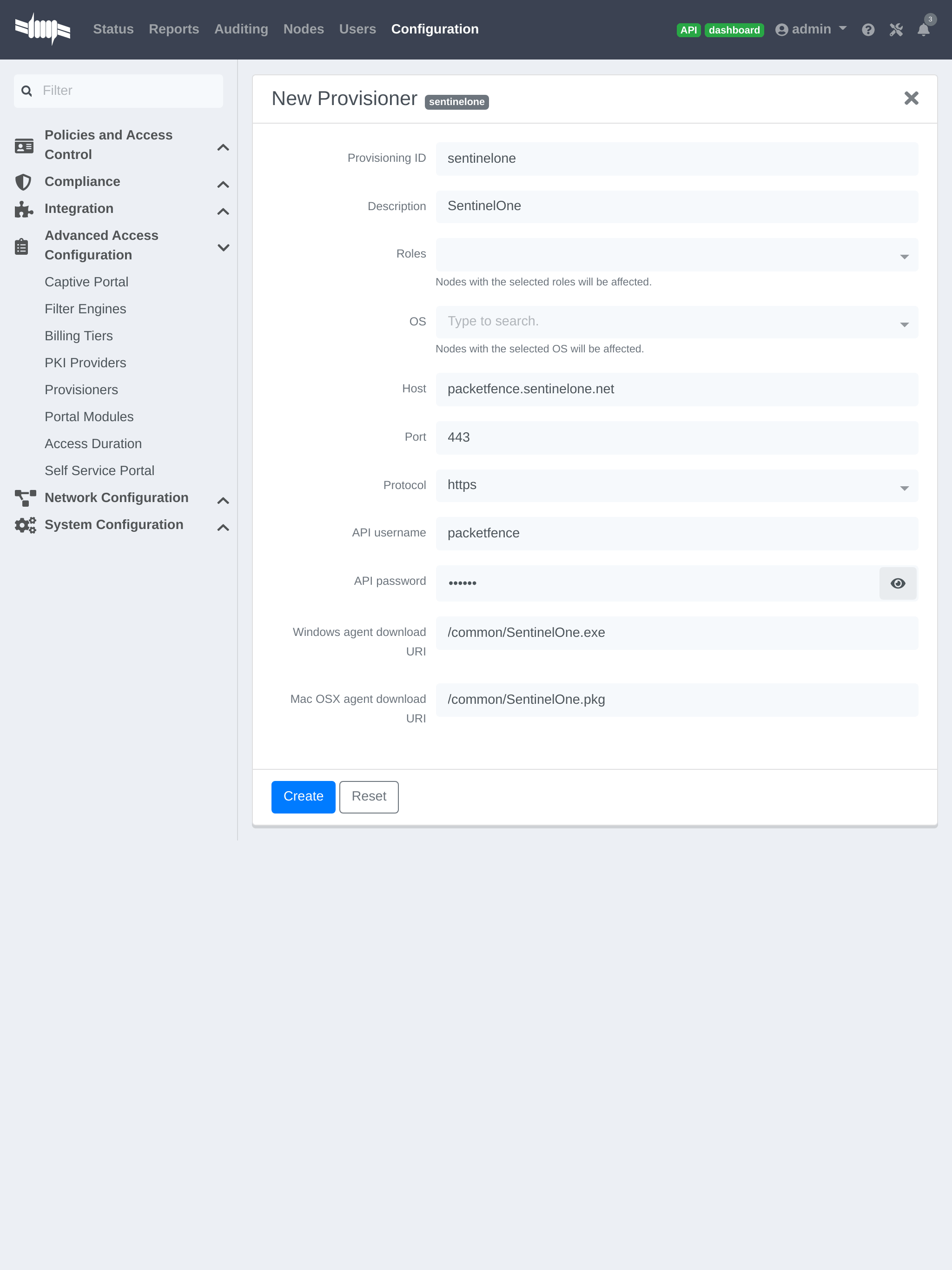
Where:
- 'Provisioning ID' is the user-defined identifier of the provisioner.
- 'Description' is a user friendly description of the provisioner.
- 'Host' is the hostname of your SentinelOne instance.
- 'Port' should be left to default unless your SentinelOne management console is on another port.
- 'API username' is the username of the user you created above in SentinelOne.
- 'API password' is the password of the API user.
-
'Windows agent download URI' is the URI on which the users should download the Windows agent. If you followed the path in this guide, it should be
/common/SentinelOne.exe. -
'Mac OSX agent download URI' is the URI on which the users should download the Mapf::errorc OSX agent. If you followed the path in this guide, it should be
/common/SentinelOne.pkg.
Add the provisioner to the profile
Now that you have created the provisioner, go in the 'Connection Profiles' menu on the left and select the default connection profile. Click 'Add Provisioner' and select the new SentinelOne that was created earlier.
Once you have completed the configuration, you need to restart pfdns in order for the SentinelOne specific passthroughs to be taken into consideration.
# /usr/local/pf/bin/pfcmd service pfdns restart
21.3.4. Testing
You can now test that the installation of the SentinelOne client is mandatory after the device registration. Connect a device to your test network and register like you normally would. At the end of the registration process you will be presented a page asking you to install the SentinelOne client on your device. After you install the client click continue. If your access is enabled then this means the connectivity between PacketFence and SentinelOne is good.
PacketFence polls SentinelOne at a regular interval (30 seconds by default) to find devices that have uninstalled their agent. When it detects them as uninstalled, it automatically brings the device back to the portal so the agent is installed.
Everytime your device connects to PacketFence using RADIUS, it schedules a provisioning check to occur 2 minutes after the connection (controlled via security event 1300002). If the agent is inactive on the device or was uninstalled, PacketFence will bring the device back to the portal so the agent is installed again or brought back to an active state.
21.4. Microsoft Intune
21.4.1. Configure from the Azure portal
Connect to Azure portal and verify Intune licenses.
Creating the application
After portal login, create application to allow Graph API access.
Click 'Azure Active Directory' > 'App registrations' > 'New registration'
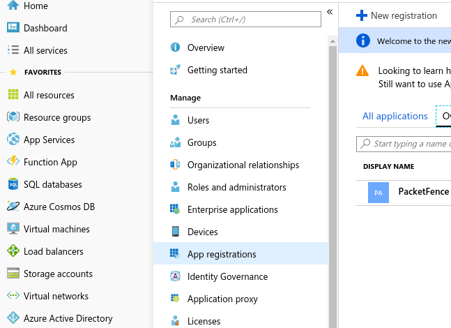
Set application name (e.g., PacketFence), choose 'Supported account types': 'Accounts in this organizational directory only', click 'Register'
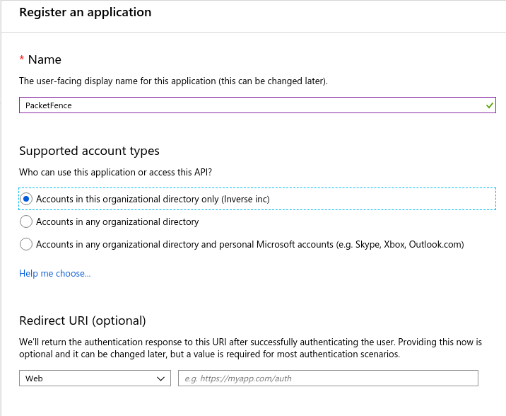
On next page, copy 'Application (client ID)' and 'Directory (tenant ID)' (needed for provisioner definition).
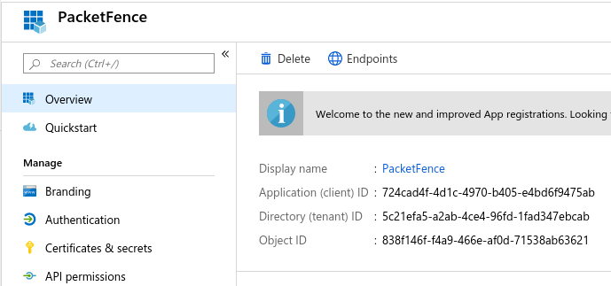
Click 'Certificates & secrets' > 'New client secret' for application password (save immediately; won’t be available later).
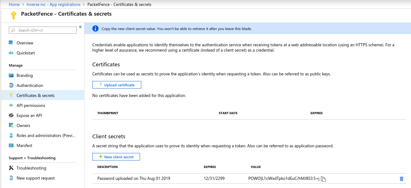
Add API permissions: click 'API permissions' > 'Microsoft Graph', select 'Application permissions', add:
Device.ReadWrite.AllDeviceManagementManagedDevices.Read.All
And click on 'Grant admin consent for (Name of your app)'
21.4.2. Configure PacketFence
Create a new provisioner
Login to the admin interface, then go to Configuration → Advanced Access Configuration → Provisioners. Click 'Add provisioner' then select Microsoft Intune.
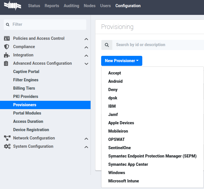
Now configure this new provisioner with the information you got above.
- The Provisioning ID is the friendly name of the provisioner.
- The Application ID is the 'Application (client ID)'.
- The Application Secret is the 'Client secret'.
- The Tenant ID is the 'Directory (tenant ID)'.
- The Client Secret is the secret of the application you created in the developer account.
- The default host should work.
- The default Login URL should work.
- The port and protocol should be left to default.
- The 'Agent download URI' should be ok.
- Authorized domains need to be adapted to allow the device to reach the download URI (per example google play needs multiple domains to be able to install the agent).
Add the provisioner to the profile
Now that you have created the provisioner, go in the 'Connection Profiles' menu on the left and select the default portal. Click 'Add Provisioner' and select the new Microsoft Intune provisioner that was created earlier.
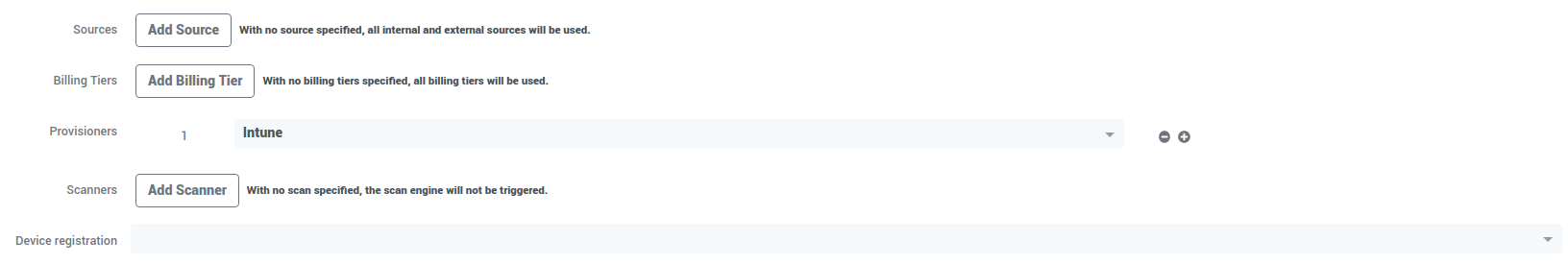
21.4.3. Testing
You can now test that the installation of the Microsoft Intune client is mandatory after the device registration. Connect a device to your test network and register like you normally would. At the end of the registration process, you will be presented a page asking you to install the Intune client on your device. After you install the client click continue. If your access is enabled then this means the connectivity between PacketFence and Azure is good.
21.5. Google Chromebook Provisioner
21.5.1. Creating a service account JSON config
In order to communicate with the Google API you must configure a service account, and download JSON security keys, and create a user to impersonate with the proper permissions.
These instructions have been adapted from https://developers.google.com/identity/protocols/oauth2/service-account.
- Open the Service accounts page https://console.developers.google.com/iam-admin/serviceaccounts.
- If prompted, select a project, or create a new one.
- Click add Create service account.
- Under Service account details, type a name, ID, and description for the service account, then click Create.
- Click on the newly created service account.
- Click on SHOW DOMAIN-WIDE DELEGATION
- Select Enable Google Workspace Domain-wide Delegation
- Save
- Copy the Client ID provided
- Click on Keys > Add Key > Create New Key > Key Type JSON > Create.
- Note where the JSON file is stored.
21.5.2. Delegating domain-wide authority to the service account
- Go to https://admin.google.com/ click on the Main Menu > Security > API Controls.
- Scroll down to the Domain wide delegation pane, select Manage Domain Wide Delegation.
- Click Add new.
- In the Client ID field, enter the newly created service account’s Client ID.
- In the OAuth scopes (comma-delimited) field, enter the scope https://www.googleapis.com/auth/admin.directory.device.chromeos.readonly
- Click Authorize.
21.5.3. Create Role
- Go to https://admin.google.com/ click on the Main Menu > Account > Admin roles.
- Click 'Create new role'
- Enter Name and Description click 'CONTINUE'
- Search for the Admin console privilege 'Manage Chrome OS Devices (read only)'
- Select 'Manage Chrome OS Devices (read only)' then click 'CONTINUE'
- Click 'CREATE ROLE'
21.5.4. Create a user if needed.
- Go to https://admin.google.com/ click on the Main Menu > Directory > Users.
- Click 'Create new user'
- Enter First Name, Last Name and Primary email. then click 'ADD NEW USER'.
21.5.5. Assign Role to a user.
- Go to https://admin.google.com/ click on the Main Menu > Directory > Users.
- Select user for service account
- Click 'Admin roles and privileges'
- Assign the Role previously created.
21.6. Configure PacketFence
21.6.1. Create a new provisioner
Login to the admin interface, then go to Configuration → Advanced Access Configuration → Provisioners → New provisioner → Google Workspace Chromebook.
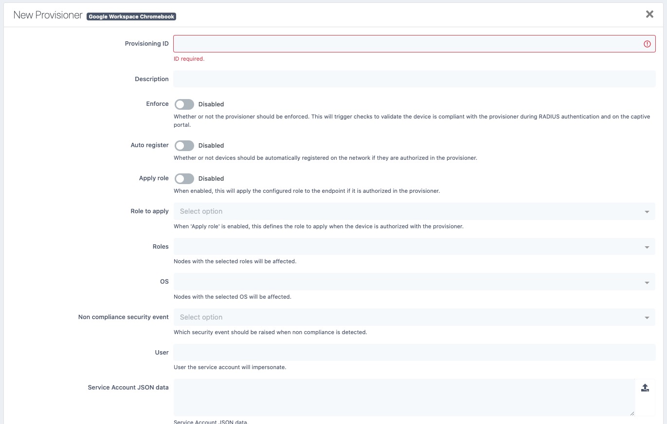
Now configure this new provisioner with the information you got above.
- The Provisioning ID is the friendly name of the provisioner.
- User for service account to impersonate.
- The JSON security keys for Service Account created.
21.7. Kandji
21.7.1. Configure Kandji
First of all you will need to configure the basic functionality of Kandji using their documentation and enable a blueprint to apply on your devices.
21.7.2. Create an API token
Next, we will need a user that has the rights to access the Kandji API in order to verify the state of the devices directly from PacketFence.
In the Kandji admin panel, first go in the 'Settings' tab and then in 'Access'.
Note down the value of Your organization’s API URL for usage in the
PacketFence configuration.
Now, click 'Add token' under 'API token'.
Create your API token by giving it a meaningful name and you will then be presented the API token
Note the API token for usage in the PacketFence configuration, then hit 'Next'.
21.7.3. Configure the API permissions
After creating your API token, you will be offered the option to configure the API permissions for the token, you should select the following permissions:
-
Device list (
/devices) -
Device ID (
/devices/{device_id})
21.7.4. Configure PacketFence
In PacketFence, MDM are referred to as provisioners. This will walk you through adding Kandji as a provisioner.
Create the provisioner
Login to the admin interface, then go to Configuration → Advanced Access Configuration → Provisioners. Click 'Add provisioner' then select 'Kandji'.
Now configure this new provisioner with the information you got above.
- The API token is the token you obtained in the instructions above
-
The host is obtained by the value of your organization’s API URL. For example, if your API URL is
https://foo.clients.us-1.kandji.io/api/v1/, the host will befoo.clients.us-1.kandji.io - The enroll URL can be obtained in the 'Add devices' menu of the Kandji admin panel under 'Enrollment Portal Link'
Add the provisioner to the connection profile
In order for the provisioner to be used by your captive portal you need to add it in its configuration. Go in 'Connection Profiles', then select the portal you want to modify and add your new provisioner in the list.
21.7.5. Add the necessary passthroughs
Next, still in the PacketFence administration console, go in 'Fencing' in the left menu, then scroll then to 'Passthroughs'.
Check the 'Passthrough' box above the field and add the following domains to the passthrough list.
-
<your instance>.<your region>.kandji.io(this is your API URL) -
*.devices.<your region>.kandji.io(you can obtain your region from the API URL) -
*.hs-analytics.net -
*.hs-banner.com -
*.hs-scripts.com -
*.hsadspixel.net -
*.hubapi.com -
*.hubspot.com -
*.kandji.io -
*.push.apple.com -
*.usemessages.com -
*.web-api.kandji.io -
albert.apple.com -
deviceenrollment.apple.com -
deviceservices-external.apple.com -
gateway.icloud.com -
gdmf.apple.com -
gs.apple.com -
humb.apple.com -
identity.apple.com -
iprofiles.apple.com -
kandji-prd-managed-library-items.s3.amazonaws.com -
kandji-prd.s3.amazonaws.com -
mdmenrollment.apple.com -
setup.icloud.com -
sq-device.apple.com -
static.ips.apple.com -
tbsc.apple.com -
time-ios.apple.com -
time-macos.apple.com -
time.apple.com -
vpp.itunes.apple.com
Restart PacketFence
Then run the following commands so that passthroughs become effective:
/usr/local/pf/bin/pfcmd configreload hard/usr/local/pf/bin/pfcmd service pfdns restart
21.7.6. Testing
You can now test that Kandji enrollment is mandatory after the device registration. Connect a device to your test network and register like you normally would. At the end of the registration process you will be presented a page asking you to install the Kandji MDM on your device. After you install the agent click 'Continue'. If your access is enabled than this means the connectivity between PacketFence and Kandji is good.
22. PKI Integration
22.1. Microsoft PKI
This section provides quick start configuration for Microsoft PKI with PacketFence. For advanced EAP-TLS troubleshooting, refer to EAP-TLS, RADIUS and OpenSSL documentation.
22.1.1. Assumptions
- PacketFence 5.4 or later server
- Properly configured switch or access point with 802.1X support
- Working PacketFence RADIUS server
- Microsoft Windows 2008 R2 Enterprise server
- PacketFence management IP: 192.168.1.5
- RADIUS shared secret: "useStrongerSecret"
- <ServerDNSName> indicates FQDN requirement for MSPKI services (not IP address)
22.1.2. Installation
Install Active Directory Certificate Service (ADCS)
For the integration with PacketFence, the following subroles need to be installed in ADCS:
- Certification Authority Web Enrollment
- Network Device Enrollment Service
- Online Responder
Apply required hotfix before configuration. After ADCS service restart, servers cannot enroll certificates and display "The RPC Server is unavailable" error. Hotfix: https://support.microsoft.com/en-us/kb/2633200
Communication between the MSPKI and PacketFence will be using port 80.
Configuring Network Device Enrollment Service (NDES)
Configure Network Device Enrollment Service (NDES) for ADCS deployment. NDES enables certificate exchange with MSPKI server via Simple Certificate Exchange Protocol (SCEP).
All configuration changes require administrative privileges.
Challenge Password
Microsoft SCEP (MSCEP) includes default challenge passwords, unique and dynamically generated for each enrolling device. In BYOD deployments, this creates barriers as users cannot self-register without administrator intervention. With NDES and PacketFence, certificate security relies on credentials for enrollment system access.
Disable challenge password by modifying Windows registry key:
Click Start and enter regedit.
Navigate to
Computer→HKEY_LOCAL_MACHINE→SOFTWARE→Microsoft→Cryptography→MSCEP→EnforcePassword.
Change the value of EnforcePassword to 0 (default is 1).
Extend URL length for the request
Best practices recommend extending URL length to avoid longer request issues.
Enter this command in NDES server CLI:
%systemroot%\system32\inetsrv\appcmd.exe set config /section:system.webServer/security/requestFiltering /requestLimits.maxQueryString:"16384" /commit:apphost
Certificate Template
Deliver certificates for user Authentication using specific template setup.
Certificate template requires these minimum Enhanced Key Usage and Key Usage
settings:
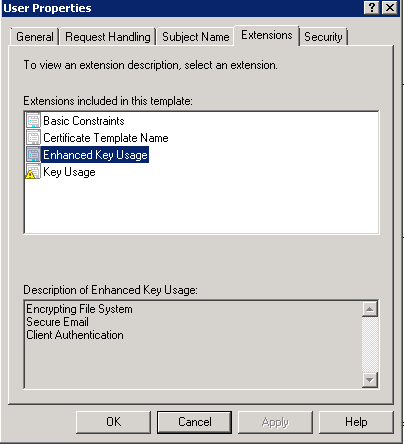
Duplicate template with configured Key Usage and Enhanced Key Usage.
Duplicate User template and modify necessary settings.
Navigate to Server Manager→Roles→Active Directory Certificates
Services→Certificate templates. Right-click User template and select
Duplicate this template.
Right-click new template, select Properties. In Subject Name tab, select
Supplied in the request over Built from information in Active Directory to
prevent NDES from overwriting requested CN.
Allow NDES template usage: navigate to Server Manager→Roles→Active Directory
Certificates Services, expand <ServerDNSName>, right-click Certificate
template, choose New template to issue, select the created template.
Configure selected template in registry:
Access registry editor: press Start and type regedit.
Navigate to
Computer→HKEY_LOCAL_MACHINE→SOFTWARE→Microsoft→Cryptography→MSCEP.
Three key entries should exist:
- EncryptionTemplate,
- GeneralPurposeTemplate,
- SignatureTemplate.
Default value: IPSECIntermediateOffline. Replace each value with the created
template name.
Reboot NDES server to apply registry changes.
IIS configuration
SCEP with PacketFence requires IIS configuration changes.
Navigate to Server Manager→Web(IIS), expand Default web site, select
CertSrv→mscep. Select Authentication, double-click Anonymous
Authentication. Ensure Application pool identity is selected.
Online Certificate Status Protocol (OCSP)
For the configuration of OCSP, the following changes are necessary.
First we need to allow the use of the template OCSPResponseSigning by the
server, to do so navigate to Server Manager→Roles→Active Directory
Certificates Services, expand <ServerDNSName>, right click Certificate
template and choose New template to issue, in the list select
OCSPResponseSigning.
After the installation of OCSP we need to create a Revocation Configuration.
To create the Revocation Configuration navigate to Server
Manager→Roles→Active Directory Certificate Services and expand
OnlineResponder: <ServerDNSName>. Right click Revocation Configuration, select
Add Revocation Configuration, click Next, choose a name for the
configuration and click Next.
Choose Select a certificate for an existing enterprise CA, click Next. Click
Browse and find the enterprise CA in the list, select it, click OK and then
Next. Choose Automatically select a signing certificate, make sure
Auto-Enroll for an OCSP signing certificate is selected, then choose the
default template of OCSP which is OCSPResponseSigning in the dropdown list
next to Certificate Template:. Add providers only if a CRL is needed in addition to OCSP.
Once created, right click the revocation configuration and select Edit
properties, go to the Signing tab, then select Enable NONCE extension
support then click OK.
Make sure that the OCSP server appears in the CA settings. Right click the CA,
choose Properties. Navigate to the tab Extension, in the dropdown list
Select extension choose Authority Information Access (AIA). Make sure that
the following appears in the list of locations: http://<ServerDNSName>/OCSP.
If this entry is missing, add it via the button Add…. In this menu type the
http:// then insert <ServerDNSName> and type /OCSP, validate by clicking
OK. Also verify that Include in the online certificate status protocol(OCSP)
extension is selected.
By default OCSP has a two days delay to refresh it’s CRL information. Which
means if a certificate is revoked on MSPKI, it will take two days before
PacketFence detects the certificate is revoked. If this delay is too long,
change it on the NDES server. To do so, navigate to Server
Manager→Roles→Active Directory Certificate Service and right click
Enterprise PKI, in the menu select Options…. The delay can be changed by
modifying the value of Set CRL status to Expiring when expiring in: to the
desired value.
RADIUS Certificate Generation
Using the Microsoft PKI involves that all certificates will be delivered by the root CA of the MSPKI.
For RADIUS authentication generate a certificate for PacketFence.
To generate the RADIUS certificate, the template WebServer will be used.
The next step is to create the request (CSR), a private key from the PacketFence server and submit the CSR to the NDES server. Connect to PacketFence via SSH and type the following in the CLI to generate the CSR and sign it with the private key:
openssl req -new -newkey rsa:2048 -nodes -keyout server.key -out server.csr
The system will prompt for some information, here is an example of a valid configuration.
- CN=packetfence.local
- C=CA
- ST=QC
- Locality=Montreal
- Organization=Inverse
- Organization Unit=IT
No fields are mandatory other than the CN.
Once the CSR is created submit it to the NDES server.
To submit the request copy the content of the request (CSR) on the
MSPKI enrollment website. The URL to input the request will be:
http://<ServerDNSName>/CertSrv/.
When reaching the website, click Request a certificate, select advanced
certificate request. Paste the content of the CSR file and select the template
Web Server. Click Submit. On this page select Base 64 encoded and click
Download certificate.
This will provide the certificate (public key) for PacketFence.
Now download the CA file by reaching the following URL in a browser:
http://<ServerDNSName>/CertSrv/.
Click Download a CA certificate, certificate chain or CRL, select the CA
certificate in the list, select Base 64 as the encoding method and finally
click Download CA certificate.
Copy those files to PacketFence.
22.1.3. Configuring PacketFence
Certificate Storage on PacketFence
It is recommended to create a separate directory to separate EAP-TLS certificates from server certificates:
# mkdir /usr/local/pf/conf/ssl/tls_certs/
RADIUS EAP-TLS authentication requires three files, the CA certificate, the server certificate and the server private key.
Copy those files in the newly created folder:
- Private Key of the RADIUS server (obtained while generating the CSR)
- Certificate for RADIUS (obtained from the submitted CSR)
- CA Certificate (downloaded from the NDES website)
Ensure that the files are readable by the user pf:
# chown pf:pf /usr/local/pf/conf/ssl/tls_certs/*
RADIUS EAP-TLS and MSPKI
In order to use the certificates generated by the MSPKI, edit the radius EAP configuration file.
Edit /usr/local/pf/conf/radiusd/eap.conf and replace the following lines with
references to the new certificates in the tls configuration block:
private_key_file = [% install_dir %]/conf/ssl/server.keycertificate_file = [% install_dir %]/conf/ssl/server.pem
E.g.
private_key_file = [% install_dir %]/conf/ssl/tls_certs/server.keycertificate_file = [% install_dir %]/conf/ssl/tls_certs/server.pemca_file = [% install_dir %]/conf/ssl/tls_certs/MyCA.pem
Certificate revocation checks have to be configured in the OCSP sub-block of
tls.
For example:
ocsp {enable = yesoverride_cert_url = yesurl = "http://<MSPKI ServerDNSName or IP>/ocsp"}
Restart radiusd to regenerate the new configuration files and enable EAP-TLS using the CA signed certificates:
# /usr/local/pf/bin/pfcmd service radiusd restart
PacketFence PKI Provider Configuration
Using the PKI requires configuring the PKI providers section in the admin interface under Configuration → Advanced Access Configuration → PKI Providers. The provider configuration defines how PacketFence connects to the MSPKI and what information will be sent.
Add a new PKI provider and select SCEP.
Fill out the form for a PKI provider according to the Certificate of Authority configuration.
For the URL it will be http://<ServerDNSName>/CertSrv/mscep/.
https: scheme.No Username/Password combination is needed for this configuration.
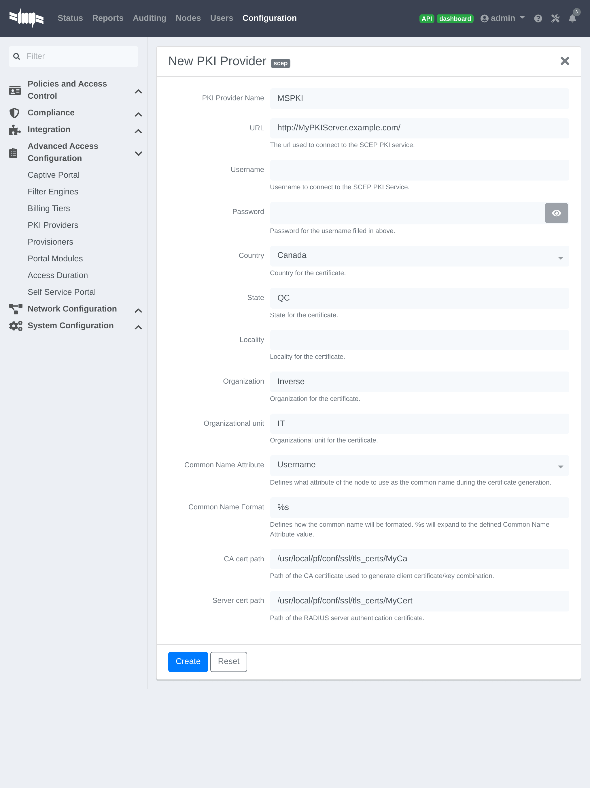
The "Server cert path" and "CA cert path" both need to be absolute (e.g.
/usr/local/pf/conf/ssl/tls_certs/MyCA.pem is an absolute path).
The "Common name attribute" field defines how the certificate will be generated and what type of "ownership" will associate the certificate to the connection. If 'MAC address' is selected, a certificate will be generated using the MAC address as the identifier. If 'Username' is selected, a certificate will be generated using the login name on the authentication backend.
Provisioners Configuration
Provisioners allow devices to automatically configure themselves to connect to the proper SSID (if applicable), use the proper authentication method (e.g. EAP-TLS) and trust the CA certificate and any certificate signed by it.
Provisioners are configured in the admin interface under Configuration → Advanced Access Configuration → Provisioners.
Add a new provisioner for each of the classes of devices to be supported amongst Android, Apple Devices and Windows. Fill out the form, choosing a different Provisioning Id per provisioner.
- Roles: The "Roles" field defines which devices will be affected by the provisioning item. If empty, all devices for this class will be affected.
- SSID: The "SSID" field defines which SSID will be configured on the device using the authentication profile.
- EAP-Type: The EAP type defines the authentication method supported and should be set to EAP-TLS to integrate with the PacketFence PKI.
- Security type: The security type should be set to WPA2 to integrate with the PacketFence PKI.
- PKI Provider: This should match the provider configured earlier in the PKI provider section.
The following is an example on how to configure an EAP-TLS connection for Windows/Android/Mac OS X/iOS
Mac OS X/iOS require the provisioning profile to be signed to remove
the untrusted warning when installing the profile. Sign it with a
Certification Authority already trusted by the device such as e.g. VeriSign.
Configuring this has to be done in the 'Signing' tab in the "Apple devices".
Fill out the fields with the contents of the Base64 encoded certificates. To extract this information from a pem formatted certificate, copy the file content.
Certificate file example:
----- BEGIN CERTIFICATE -----1234567890asdfghjklzxcvbnmqwertyuiop78----- END CERTIFICATE -----
Copy everything from the BEGIN to END lines. Repeat this operation for the certificate key and intermediate certificate.
----- BEGIN PRIVATE KEY -----1234567890asdfghjklzxcvbnmqwertyuiop78----- END PRIVATE KEY -----
Connection Profiles Configuration
Provisioners must be enabled in the Connection Profiles configuration in the admin interface.
In the admin interface, go to Configuration → Policies and Access Control → Connection Profiles, and select each of the provisioners created above which should be active for the profile. If no connection profile is defined, configure the "default" profile to use the provisioners created.
Passthroughs Required for Android
Android devices require passthroughs to be created to allow them to fetch the configuration application from the Google Play Store.
Add the following to the "Fencing" section in the admin interface Configuration tab.
passthrough=enabledpassthroughs=*.ggpht.com,*.googleusercontent.com,android.clients.google.com,*.googleapis.com,*.android.clients.google.com,*.gvt1.com
Debugging MSPKI Integration with PacketFence
This is a way to do the procedure of enrollment manually, mainly for debugging purposes.
First generate a request and its private key via the openssl command. Type following commands in PacketFence CLI:
mkdir temp; cd tempopenssl req -newkey rsa:2048 -nodes -keyout local.key -out local.csr -subj '/C=CA/ST=QC/L=Montreal/O=Inverse/OU=IT/CN=www.test.example.com'
This will create 2 files in the current directory, local.csr and local.key.
Now obtain the CA and some specific certificates from the MSPKI.
sscep getca -u http://<ServerDNSName>/CertSrv/mscep/ -c MyCA.crt
Now use the "CEP encryption" certificate and the "Enrollment agent". Both were obtained when doing the sscep getca. There should be at least three certificates with the same name and a different number at the end. e.g. MyCA.crt-0 (Enrollment agent certificate), MyCA.crt-1 (CEP encryption certificate) and MyCA.crt-2 (CA certificate).
To display the content of each certificate use following commands:
openssl x509 -in MyCA.crt-0 -textopenssl x509 -in MyCA.crt-1 -textopenssl x509 -in MyCA.crt-2 -text
In the output search for X509v3 extensions:. When using the sscep enroll command the "Enrollment agent" certificate is needed as an argument for -c and the "CEP Encryption" certificate as an argument for -e. -d is used for the debug output. -l is the local file where the certificate will be saved.
sscep enroll -c MyCA.crt-0 -e MyCA.crt-1 -k local.key -r local.csr \-l MyCert.crt -S sha1 -u http://<ServerDNSName>/CertSrv/mscep/ -d
To verify the certificate against the OCSP use the following openssl command:
openssl OCSP -issuer path/CA-Certificate -cert path/Certificate-to-verify \-text -url http://<ServerDNSName>/OCSP
Debugging Android Passthroughs
If domains need to be added to passthroughs, capture the traffic coming from the device which cannot access the Google Play Store. To do this use tcpdump for instance, collect the IP address of the device then run the following in PacketFence CLI:
tcpdump -i $REGISTRATION_INTERFACE -n dst port 53 and src host @IP_Device
This will output any DNS requests from the device to PacketFence. Find google related domains and add them to the passthroughs list.
For certificate-related issues, check logs in /usr/local/pf/logs/ as described in Log Files in the Troubleshooting section.
22.2. PacketFence PKI
This section provides quick start configuration for PacketFence PKI. For advanced EAP-TLS troubleshooting, refer to EAP-TLS, RADIUS and OpenSSL documentation. PKI comes installed by default since PacketFence version 10. All certificates are saved in database. To migrate certificates from old PacketFence PKI, see upgrade section.
22.2.1. Certificate Authority creation
Create new certificate authority. In PacketFence web administration, go to Configuration → Integration → PKI → Certificate Authorities and click New Certificate Authority.
For sub-CA configuration: click 'Generate CSR' (top right of CA form), modify information if needed, click 'Generate CSR'. Copy CSR and provide to external CA for signed certificate retrieval. Provide signed certificate and click 'Save'.
For expiring CA certificate: generate new CSR or click Resign CA Certificate (self-signed).
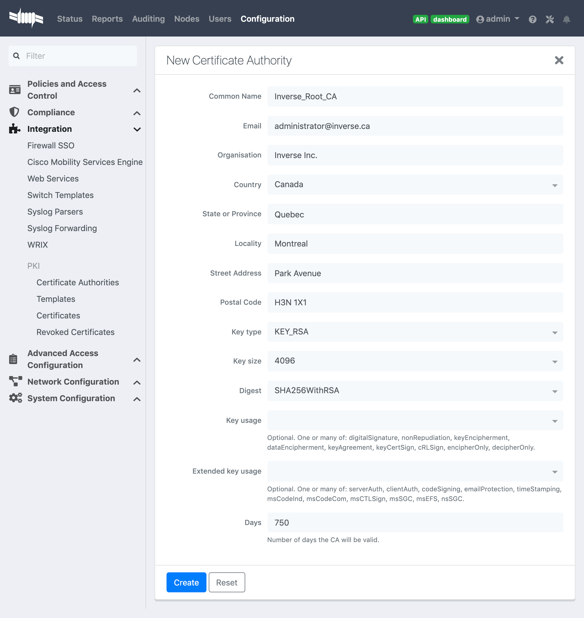
Once you have created the CA, you should see the Root CA certificate displayed at the bottom of the page:
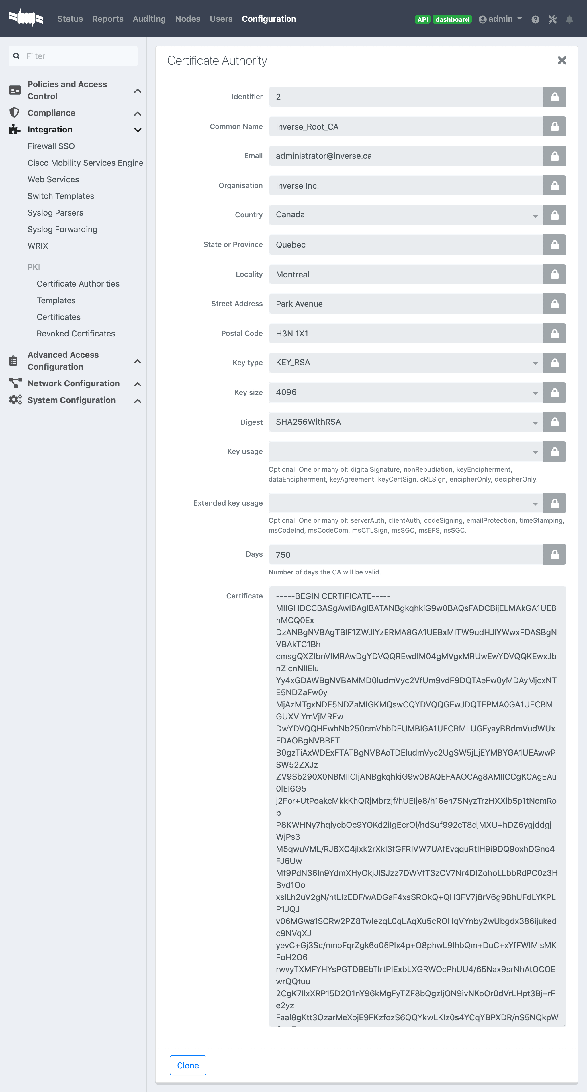
Once done copy the certificate in the clipboard from the Certificate Authorities list (Configuration → Integration → PKI → Certificate Authorities and click on Copy Certificate) then edit the RADIUS certificate section in Configuration → Systen Configuration → SSL Certificates → RADIUS → Edit and paste the public key in "Certificate Authority" and Save. (Don’t forget to restart radiusd-auth)
This will authorize the EAP TLS authentications using the PKI issued certificates.
22.2.2. Template creation
Now you will need to create a certificate template that will gather all the settings for your certificate like the validity period or the certificate usage.
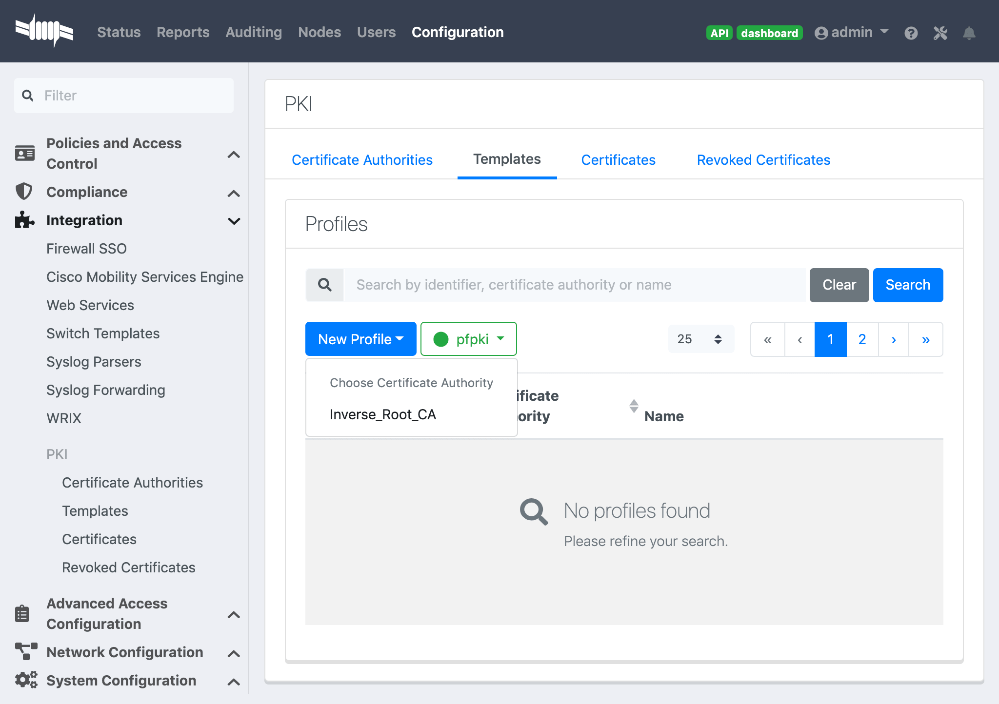
Here’s a template example:
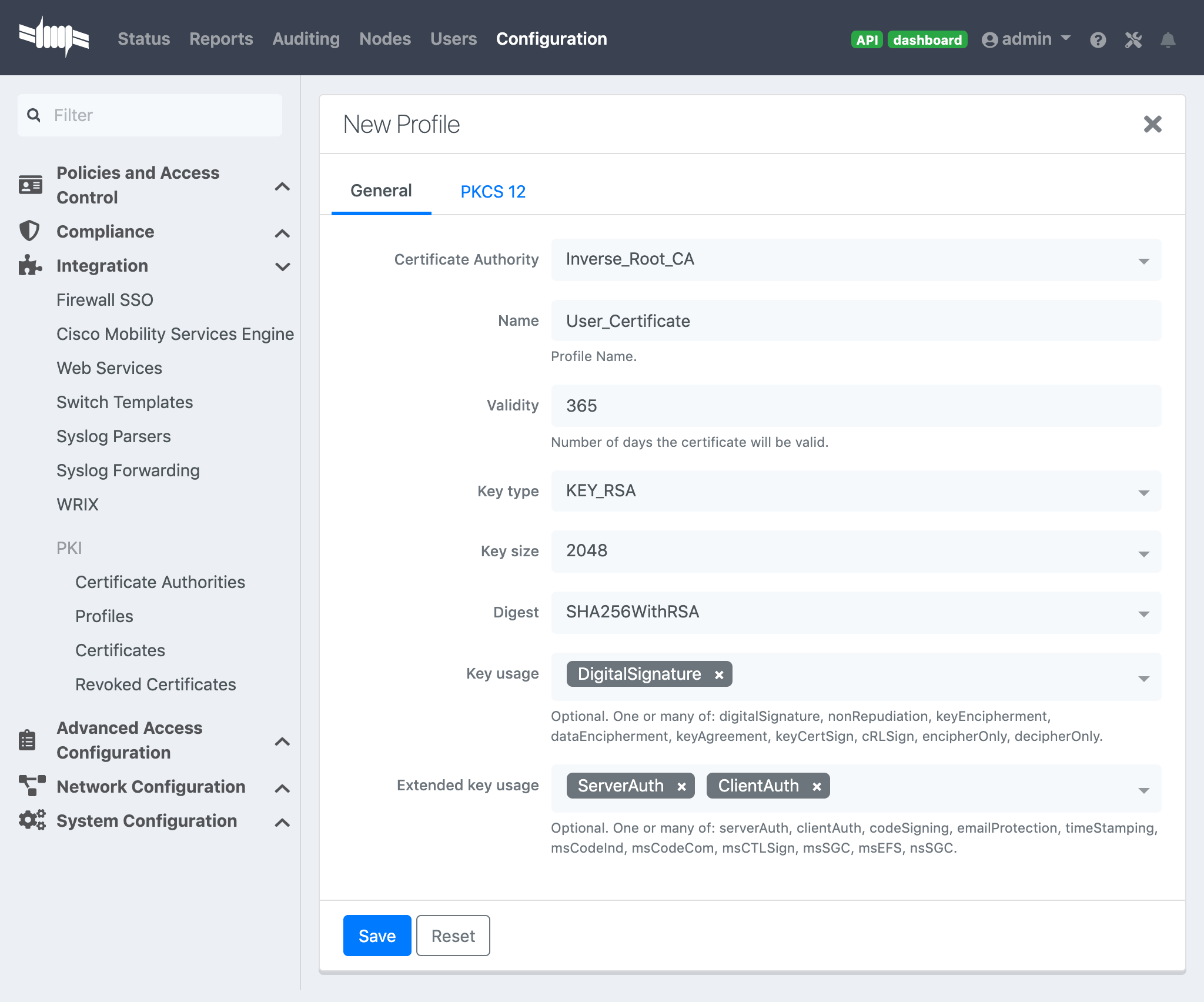
Key usage clientAuth: To use your certificate for a client authentication.
Key usage serverAuth: If you want to install your certificate on a server.
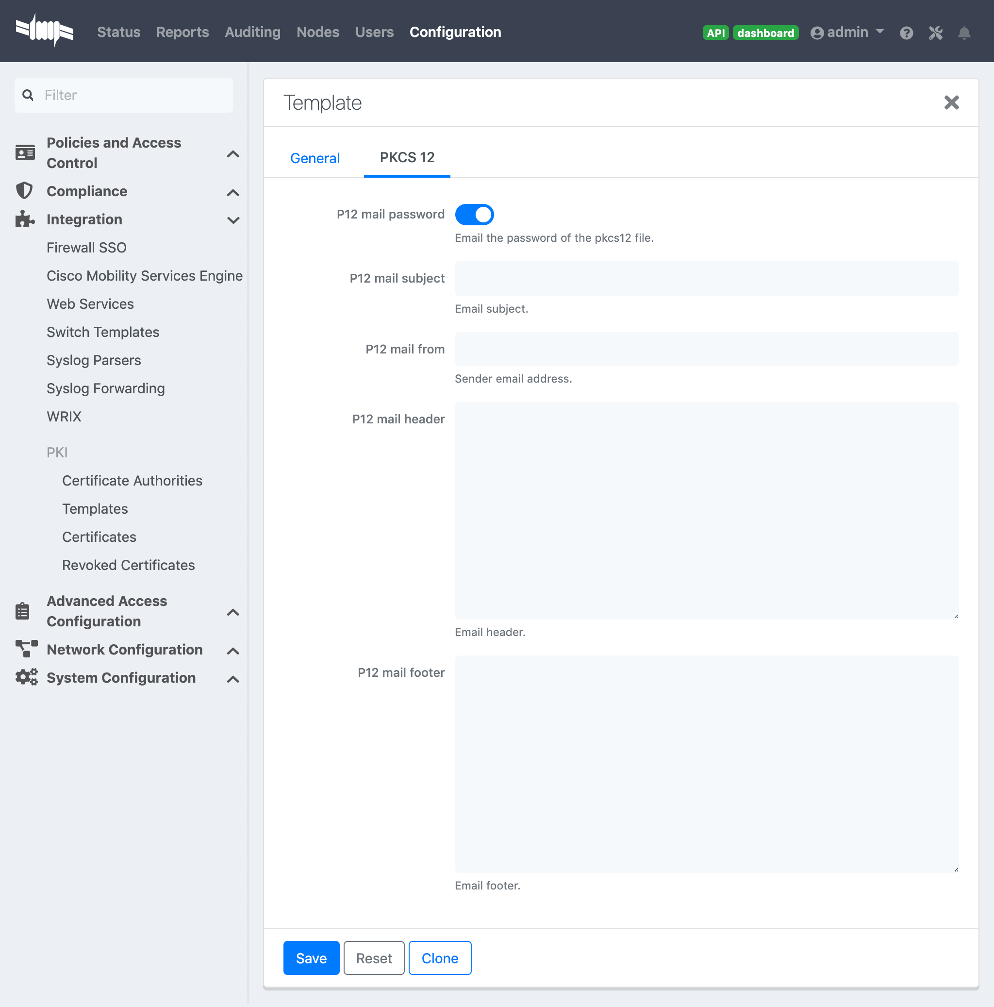
SCEP
You can choose to enable SCEP on this template.
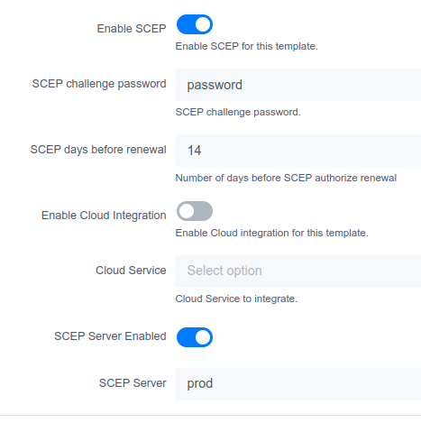
Optionally, enable 'SCEP Server Enabled' and define an external SCEP server to proxy the request.
SCEP Test
Let’s do a scep request by hand. Directly from the PacketFence server do that:
Create a private key and a csr file:
openssl req -newkey rsa:2048 -keyout PRIVATEKEY.key -out MYCSR.csr
Generating a 2048 bit RSA private key.........................................................................................................................................................................+++.........................+++writing new private key to 'PRIVATEKEY.key'Enter PEM pass phrase:Verifying - Enter PEM pass phrase:-----You are about to be asked to enter information that will be incorporatedinto your certificate request.What you are about to enter is what is called a Distinguished Name or a DN.There are quite a few fields but you can leave some blankFor some fields there will be a default value,If you enter '.', the field will be left blank.-----Country Name (2 letter code) [XX]:CAState or Province Name (full name) []:QCLocality Name (eg, city) [Default City]:MontrealOrganization Name (eg, company) [Default Company Ltd]:AcmeOrganizational Unit Name (eg, section) []:ITCommon Name (eg, your name or your server's hostname) []:acme.comEmail Address []:admin@acme.com
Please enter the following 'extra' attributesto be sent with your certificate requestA challenge password []:passwordAn optional company name []:
Get the CA certificate:
sscep getca -u http://ip_address/scep/template_name -c ./ca-prefix -i MyPKI -v -d
sscep: starting sscep, version 0.6.1sscep: new transactionsscep: transaction id: SSCEP transactionIdsscep: hostname: ip_addresssscep: directory: scep/template_namesscep: port: 80sscep: SCEP_OPERATION_GETCAsscep: requesting CA certificatesscep: scep msg: GET /scep/template_name?operation=GetCACert&message=MyPKIHTTP/1.0
sscep: server returned status code 200sscep: MIME header: application/x-x509-ca-certsscep: valid response from serversscep: MD5 fingerprint: 22:DE:09:17:8B:5F:94:1E:EB:0D:9C:12:EF:05:F0:C5sscep: CA certificate written as ./ca-prefix
Remove the private key passphrase:
openssl rsa -in PRIVATEKEY.key -out private.keyEnter pass phrase for PRIVATEKEY.key:writing RSA key
Send the CSR and retreive the certificate:
sscep enroll -c ./ca-prefix -k ./private.key -r ./MYCSR.csr -u http://ip_address/scep/template_name -S sha1 -l ./cert.crt
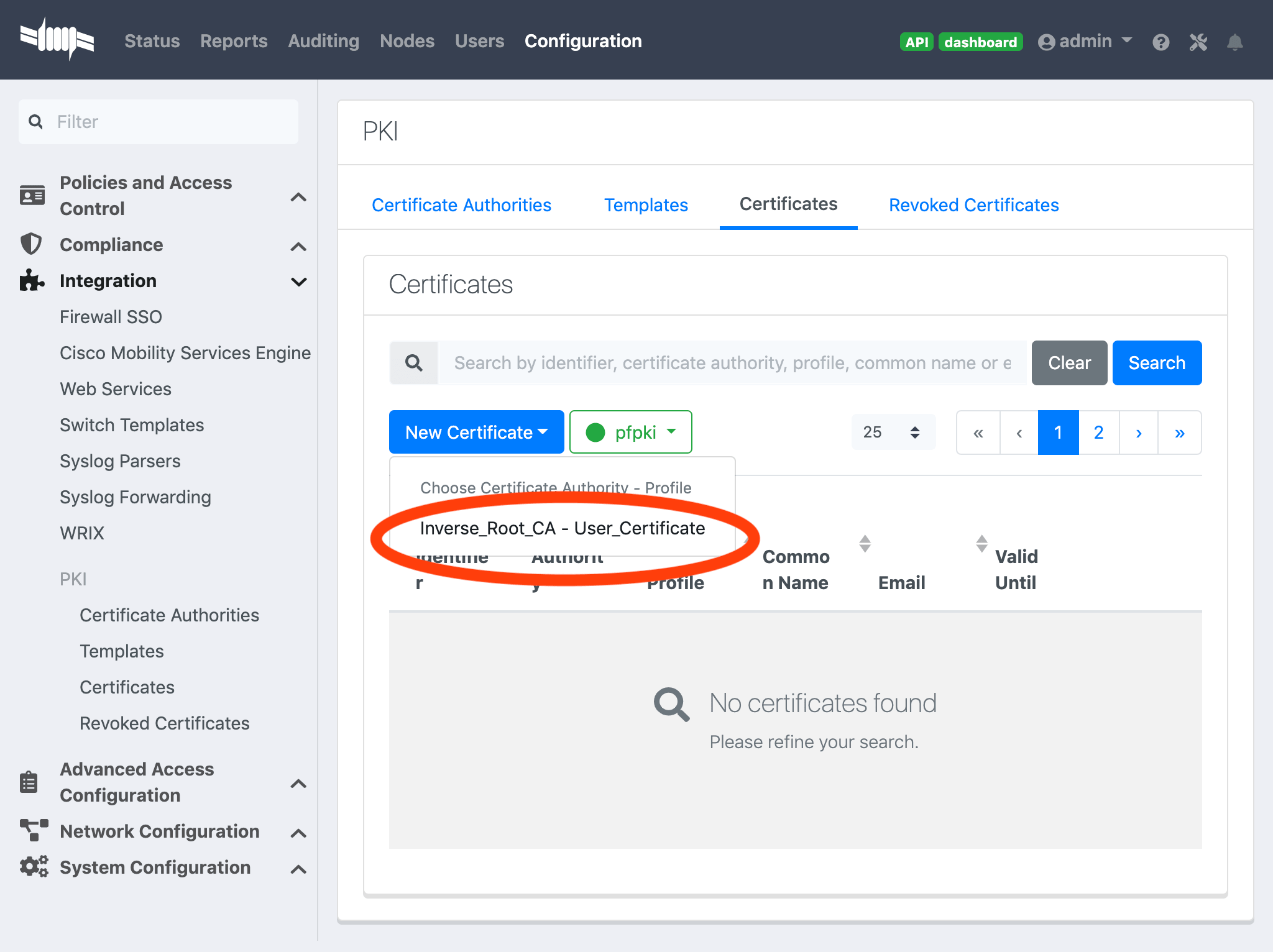
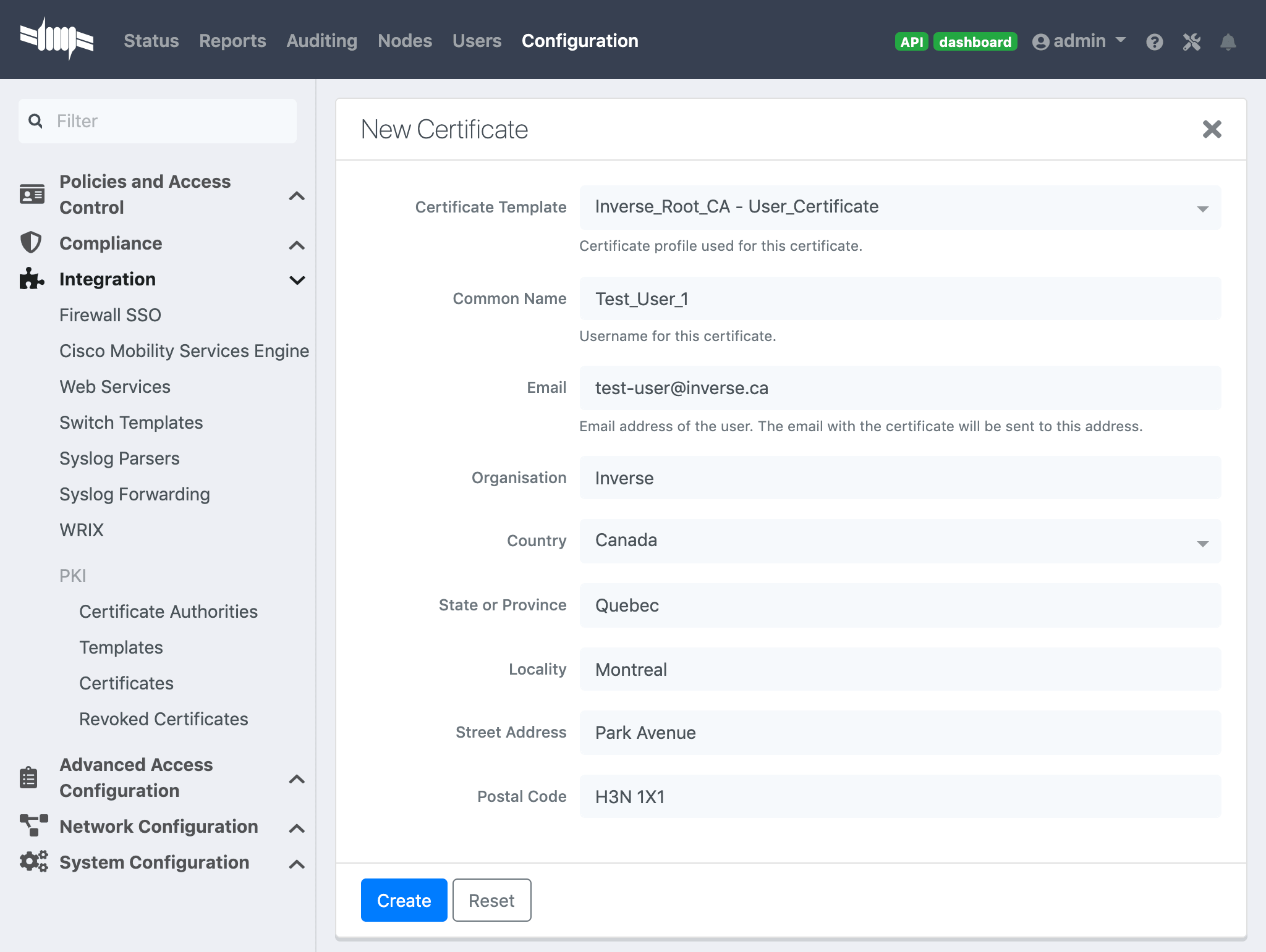
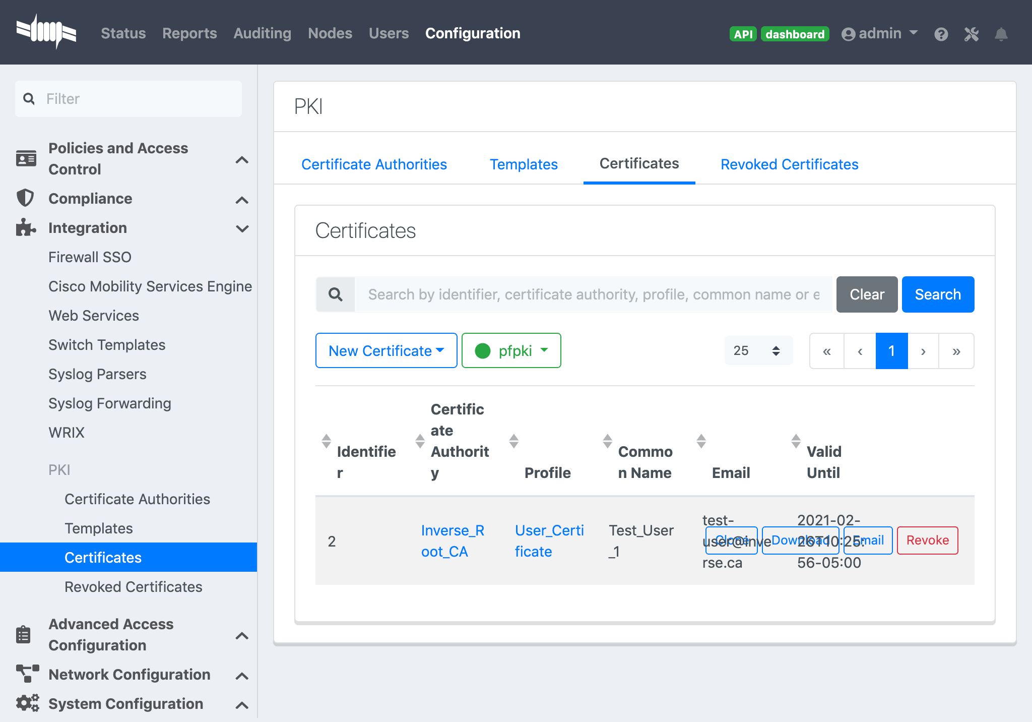
22.2.4. PEM format
The PacketFence PKI hand out PKCS12 certificates, if you want to convert your certificate to PEM format, you can use the commands:
openssl pkcs12 -in YourCert.p12 -nocerts -out YourCert.key -nodesopenssl pkcs12 -in YourCert.p12 -out YourCert.pem -clcerts -nokeys
22.2.5. Revoke a certificate
If you revoke a certificate it can’t be recovered and you would need to recreate a new one. You will need to specify a reason of the revokation.
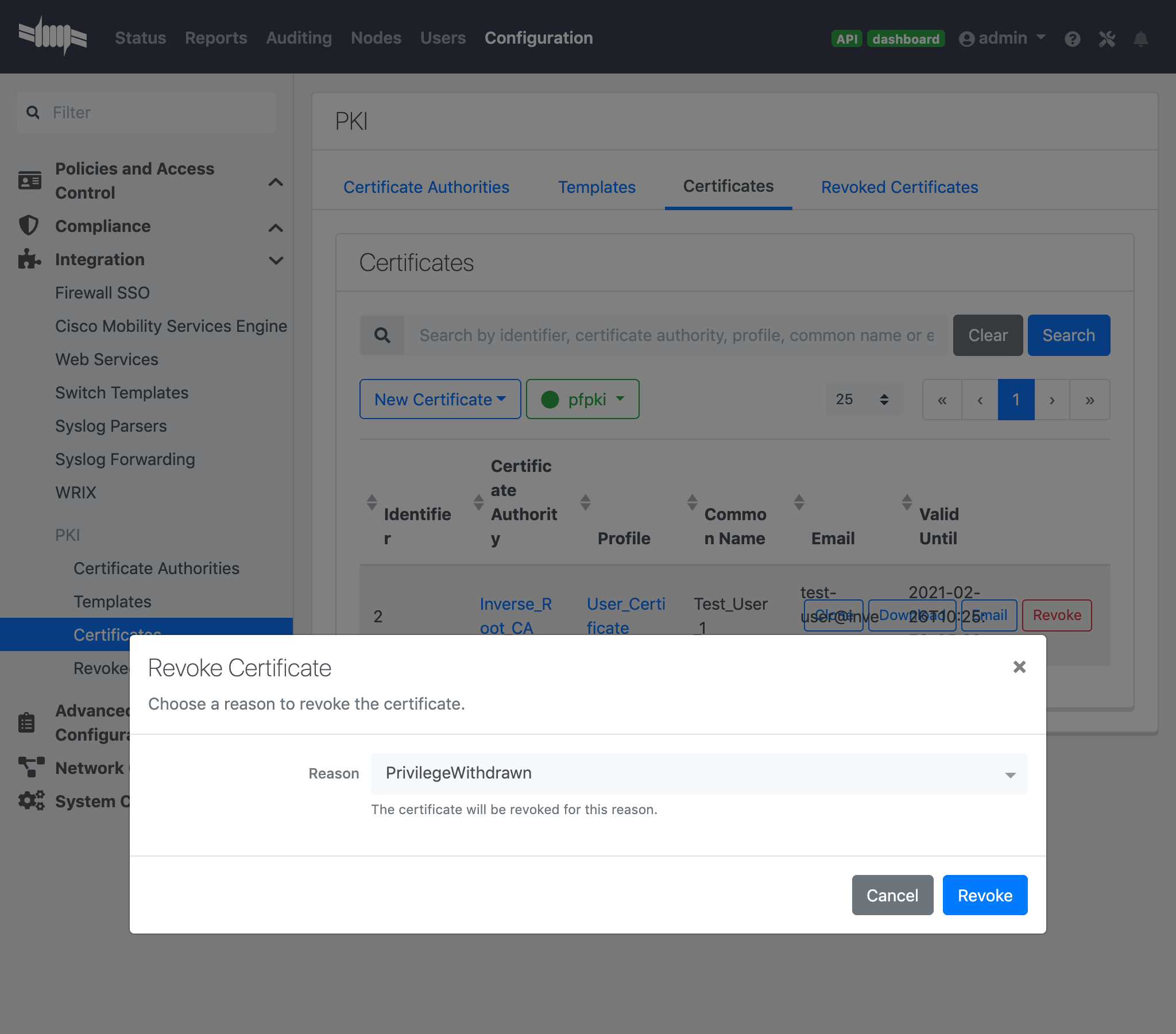
22.2.6. Resign a certificate
Resign-ing an existing Certificate will extend the duration by reusing the private-key to generate a new public certificate. Click the 'Resign' button (top-right), modify the information (if needed) and click 'Resign'.
22.2.7. PKI Provider
You can hand out certificate to non-BYOD device on a captive portal.
First, you would need to create the PKI provider that will query the PacketFence PKI for new certifcate. Go to Configuration → Advanced Access Configuration → PKI provider
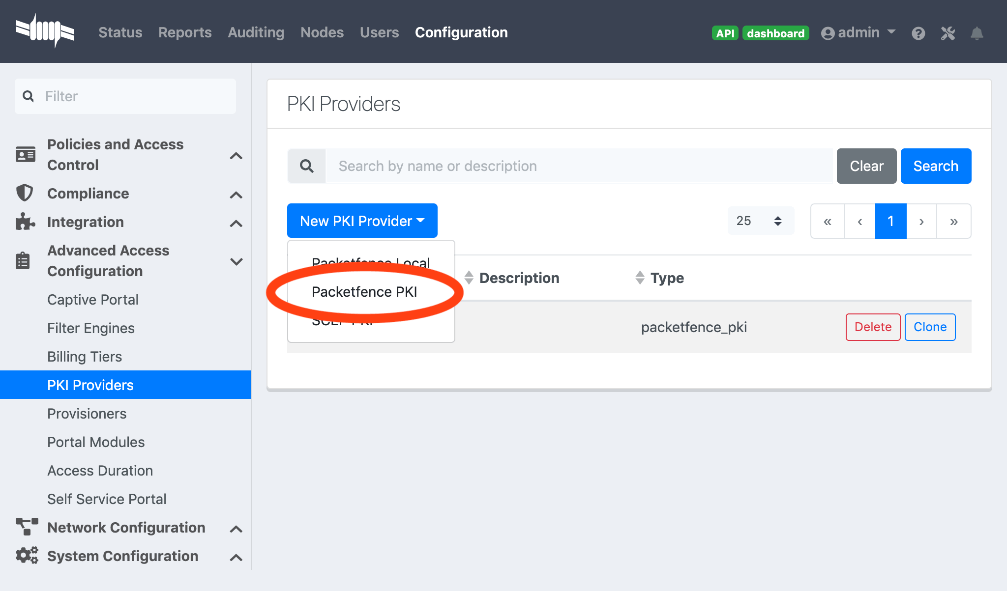
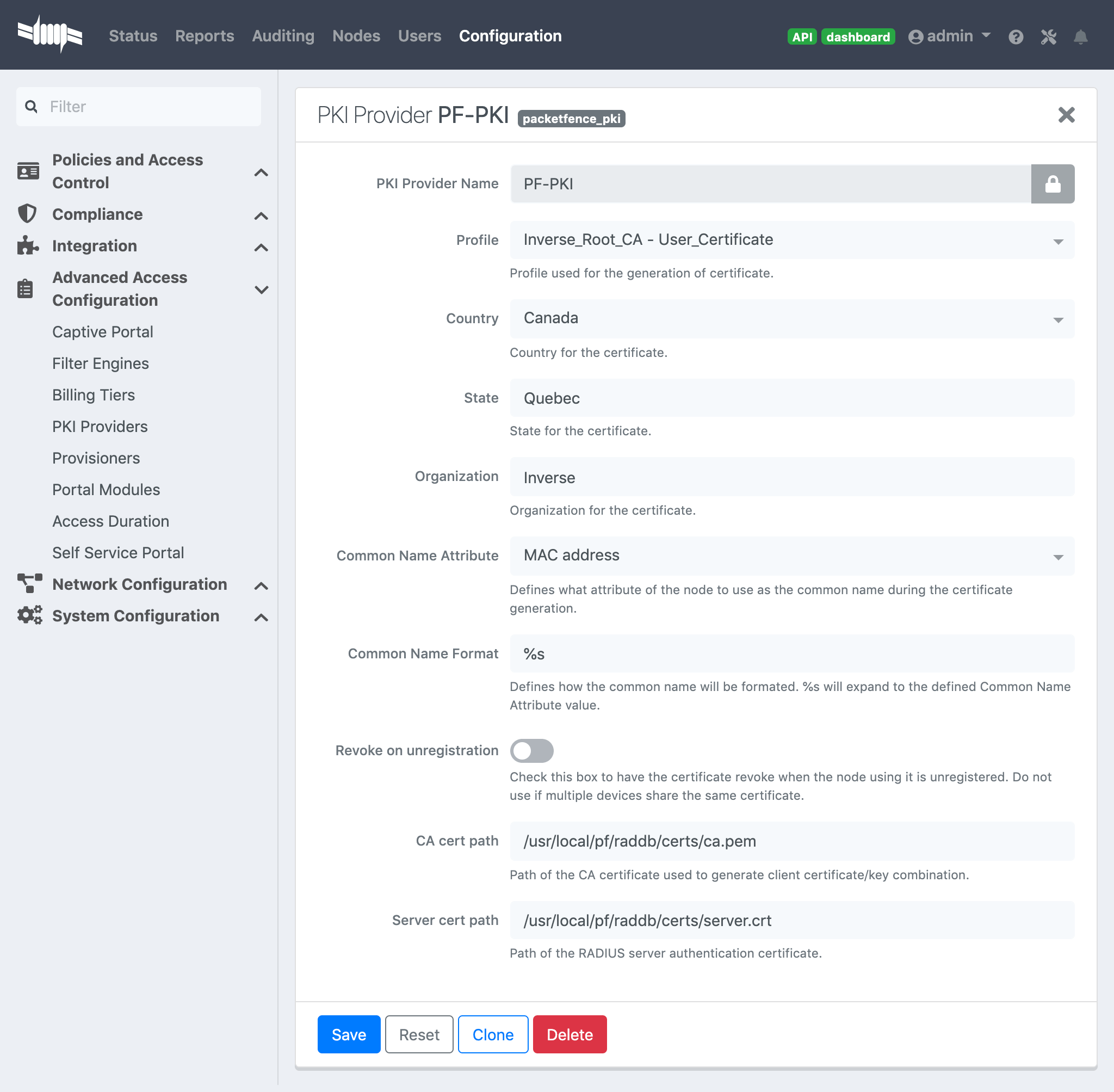
22.2.8. Intune Integration
Azure configuration
You can hand out certificates when you use intune enrolment.
First you need to create an application on Azure that allow PacketFence to connect to the Intune API.
To do that first you have to go in Azure portal and App registration then click New registration
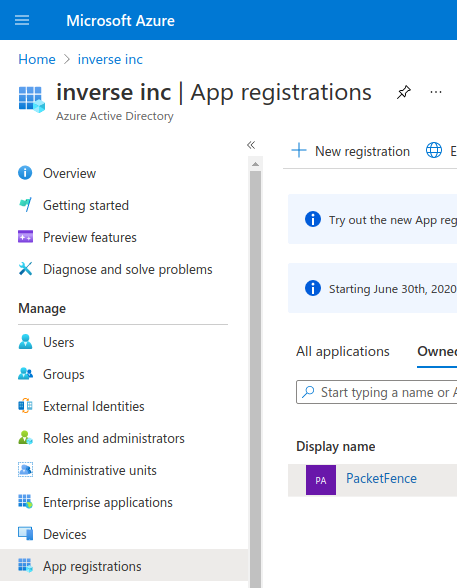
Next set a Name and in "Supported account types" select "Accounts in this organizational directory only" then click Register
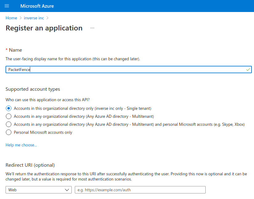
On the next page you have to copy the "Application (Client) ID" and the "Directory (tenant) ID", thoses will be needed to configure PacketFence.
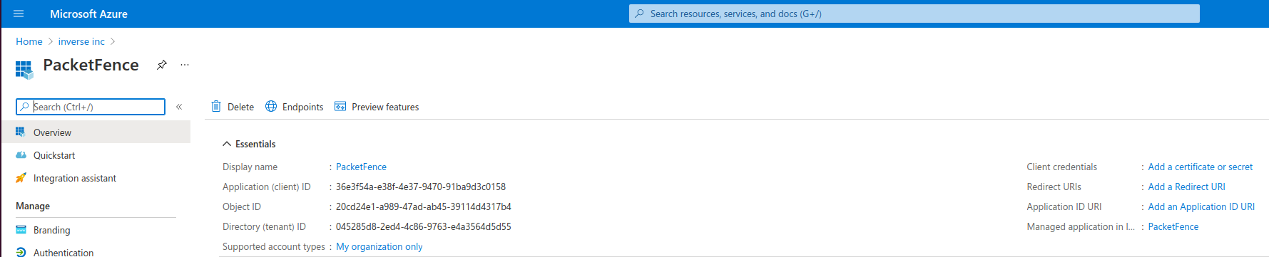
Then you need to generate a "Client secrets", to do that click on "Add a certificate or secret"
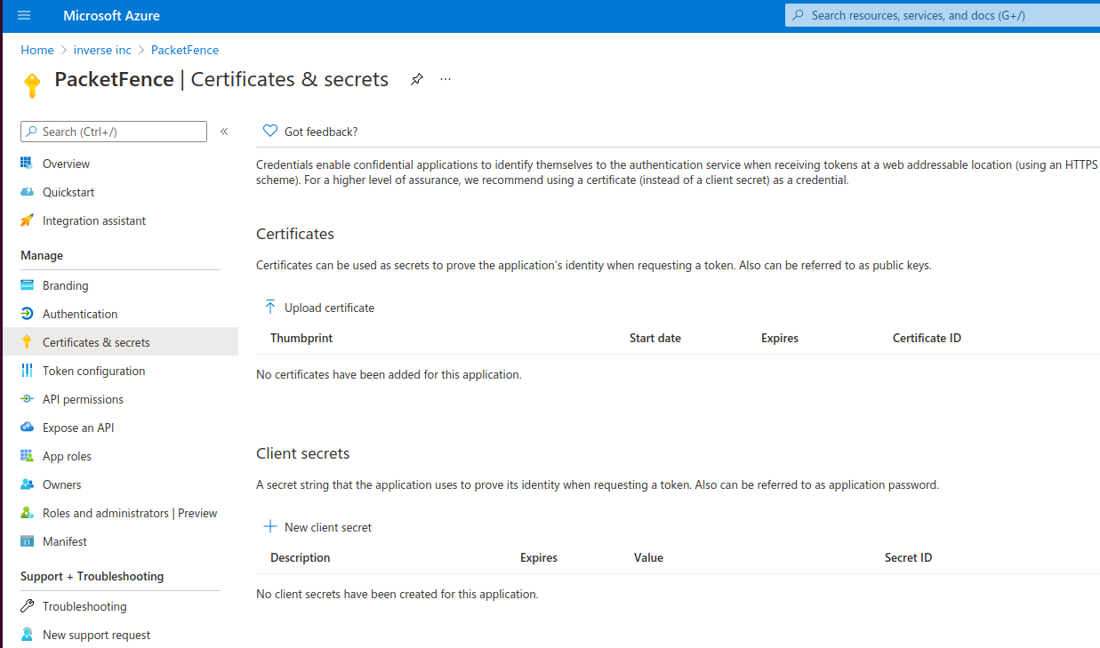
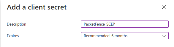
Copy the "Value" of the secret, this is the only time you should be able to see it.
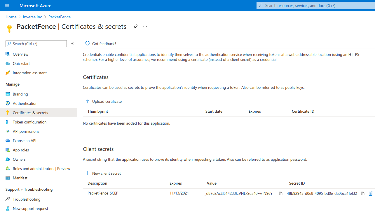
Next you have to add API permissions, click on "API permissions" → "Add a Permissions":
Intune -> "Application permissions" and select "scep_challenge_provider"Microsoft Graph -> "Application permissions" and select "Application.Read.All"Microsoft Graph -> "Delegated permissions" and select "User.Read"
For more details about permissions https://techcommunity.microsoft.com/t5/intune-customer-success/support-tip-intune-service-discovery-api-endpoint-will-require/ba-p/2428040
Previous versions used Azure Active Directory Graph which is now deprecated and will stop working after December 2022, if you have granted those permissions you must remove them and add the new permissions instead.
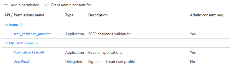
Last step is to "Grant admin", just click on "Grant admin consent for …" and click Yes
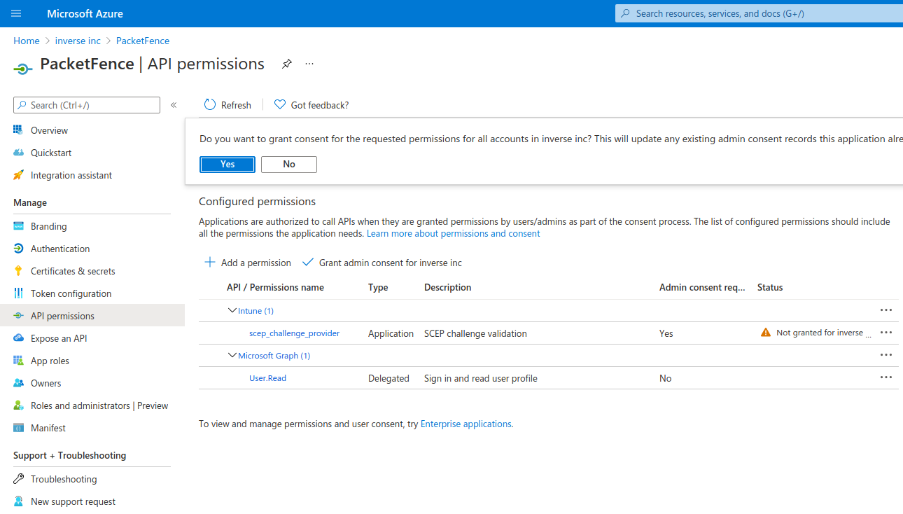
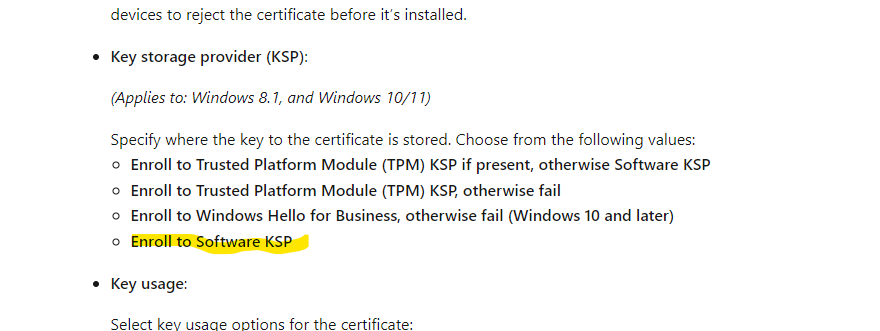
PacketFence configuration
Intune definition
First of all you have to define the configuration parameters to reach the Intune API. To do that go in Configuration → Integration → Cloud Services → New Cloud → Microsoft Intune
Next fill the field with the values taken from the Azure portal ("Application (Client) ID" , "Directory (tenant) ID" and "Client secrets") and Create.
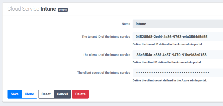
SCEP configuration
Now let’s configure the PKI template to enable SCEP on it. (go to the previous section on how to configure a template in the PKI)
Go in Configuration → Integration → PKI → Templates and edit the one you created previously.
You can see that there is a SCEP section. Enable SCEP and check Enable Cloud Integration and select the Cloud Service you created previously. (In the case the SCEP challenge password is not mandatory).
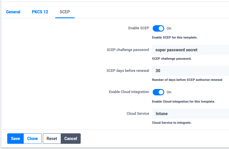
Starting from now the scep server will be available on each ip where the portal is running (you need to enable the portal on the management interface if you want to be able to do SCEP on this interface).
The URL of the SCEP server will be available on http://ip_address/scep/template_name (https too) where template_name is the name of your template in the PKI.
Intune configuration
For this section you can follow the instruction on the Microsoft web site:
https://docs.microsoft.com/en-us/mem/intune/protect/certificates-profile-scep
From the PacketFence server you will need to extract the PKI Ca certificate associated to the template and put it in Intune as a "trusted certificate"
Then set the SCEP URL to http://ip_address/scep/template_name or https://ip_address/scep/template_name
22.3. AirWatch
This section has been created to give a quick overview to configure AirWatch (VMware) with PacketFence. This guide does not include advanced troubleshooting of EAP-TLS connections. Refer to the relevant documentation of EAP-TLS, RADIUS and OpenSSL for advanced features. The PKI comes installed by default since PacketFence version 10. All certificates would be saved in the database. If you want to migrate your certificate from the old PacketFence PKI please see the upgrade section.
22.3.1. Assumptions
You have a functional PacketFence PKI and you already have created a Certificate Authority and its templates with SCEP enabled. The template used here is: 'airwatch2'
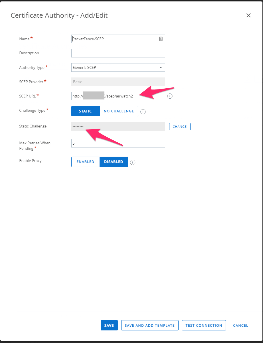
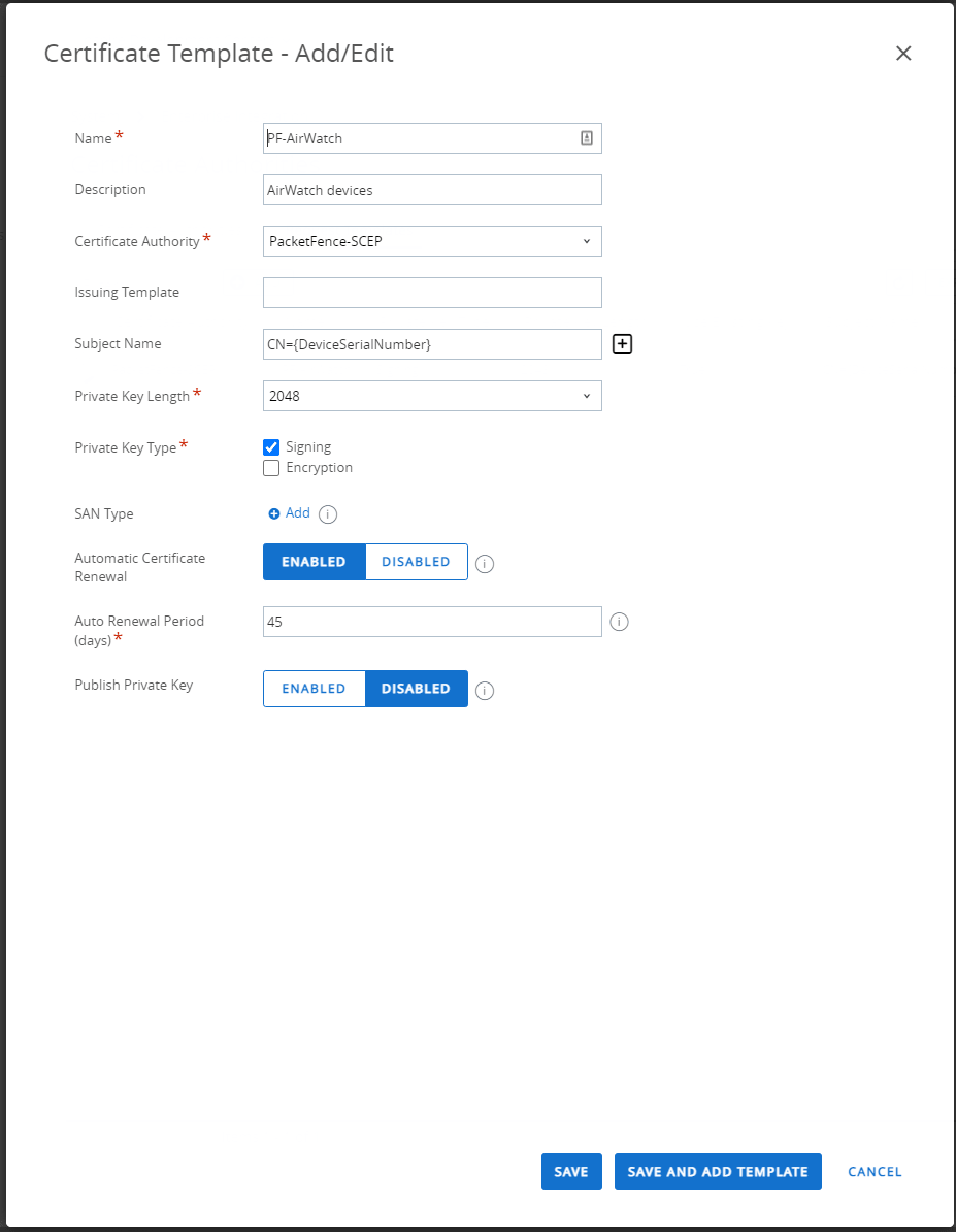
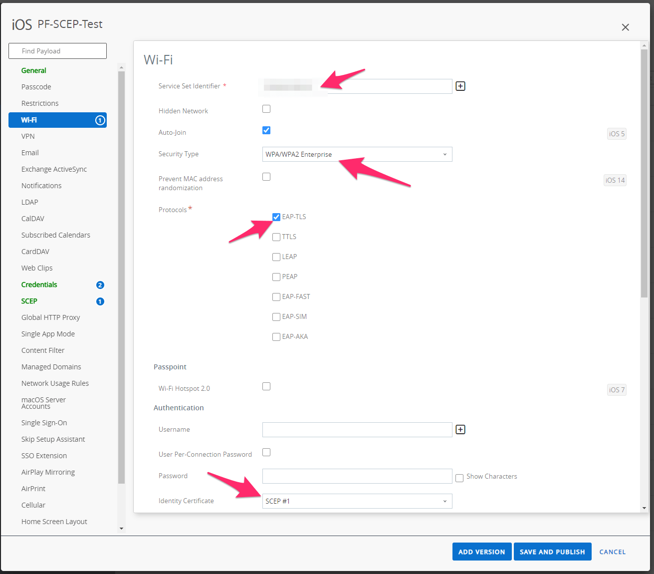
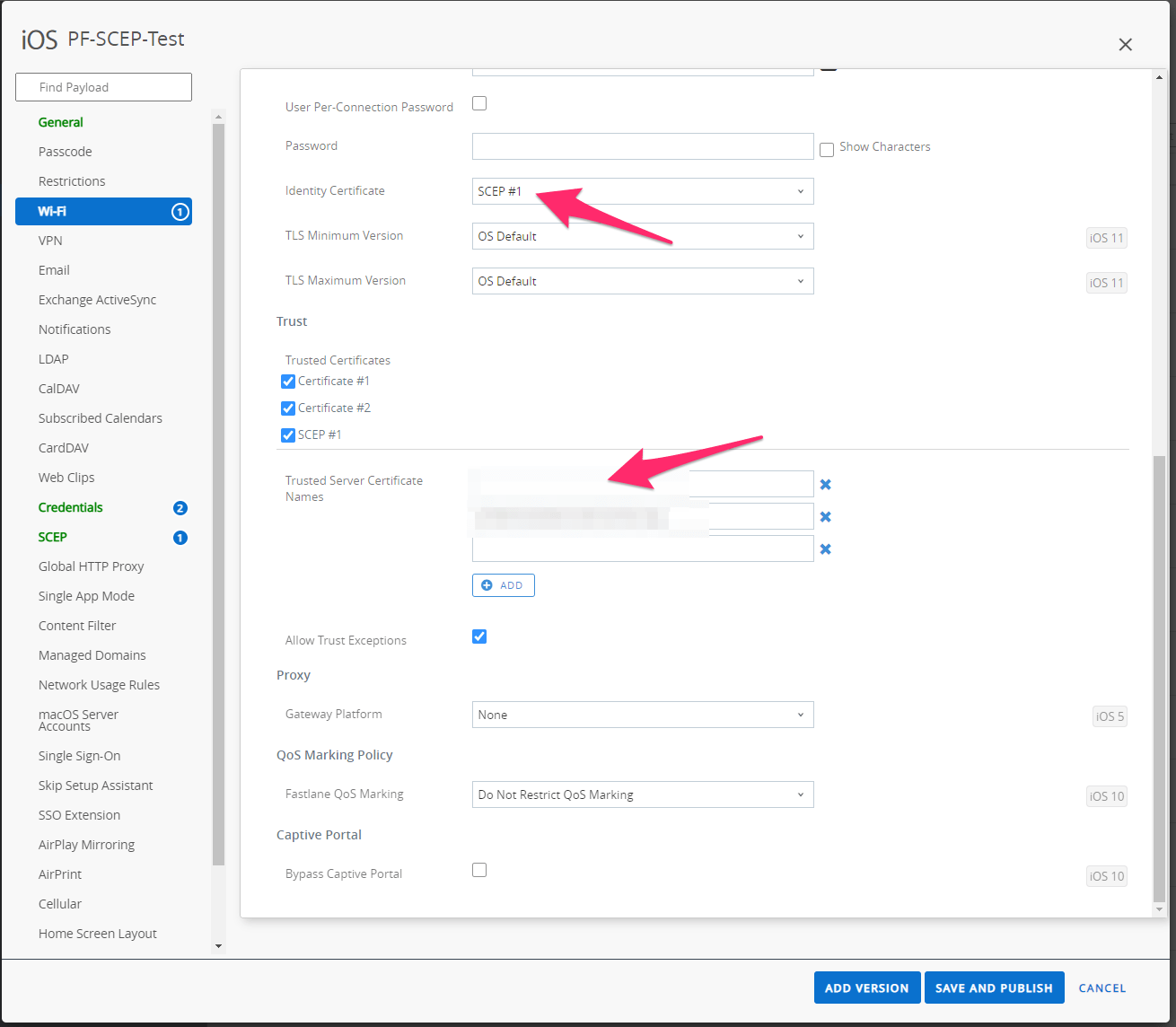
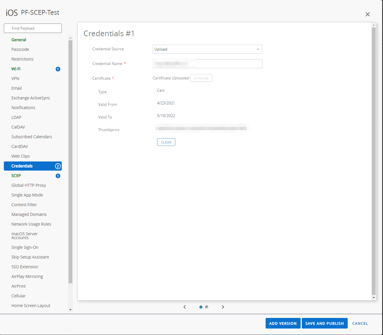
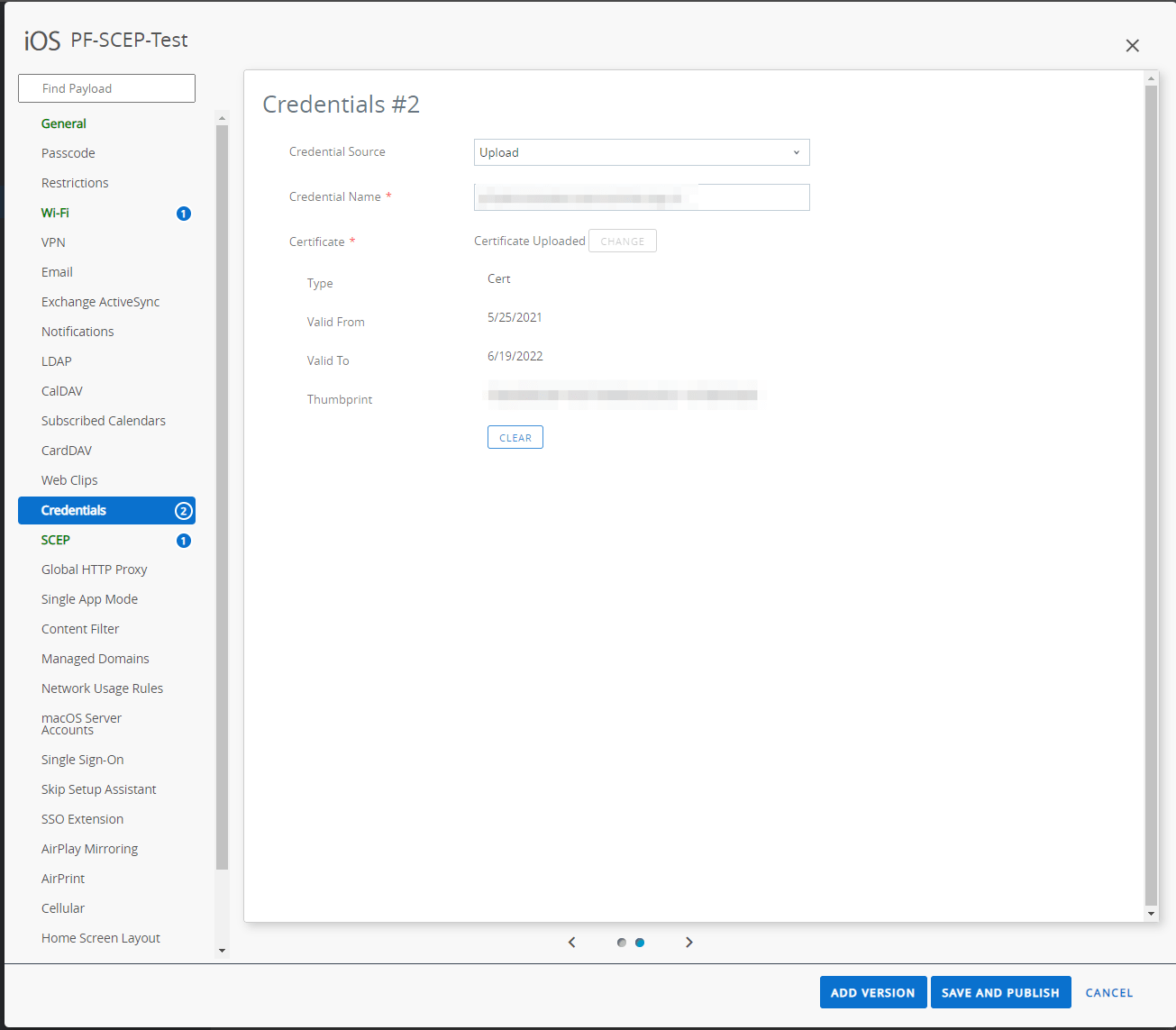
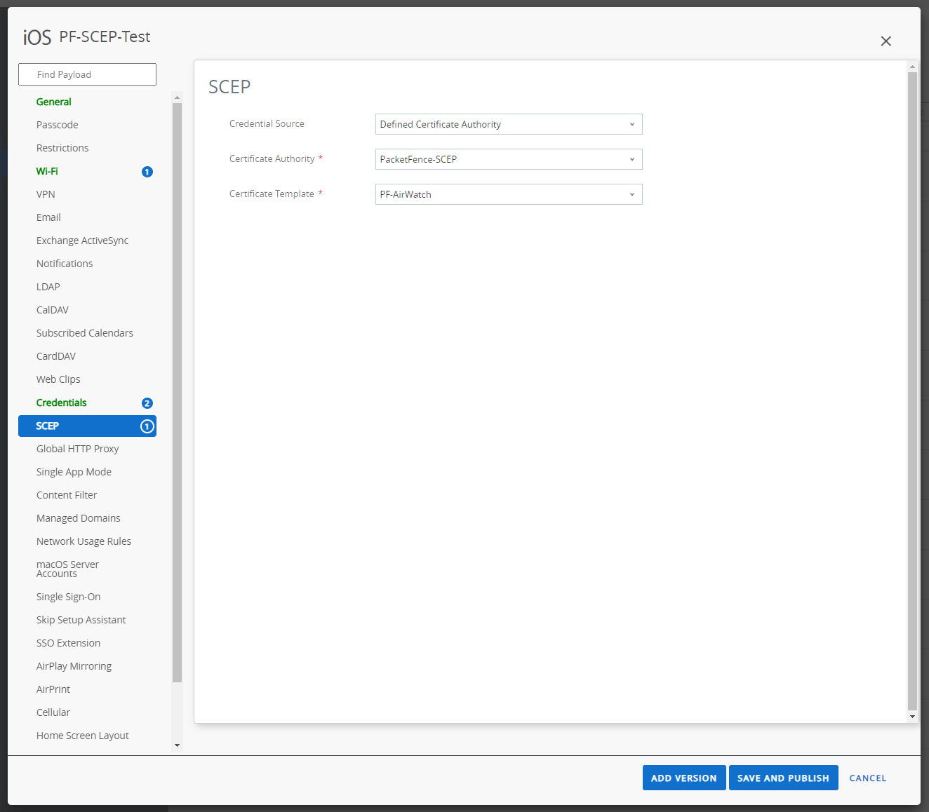
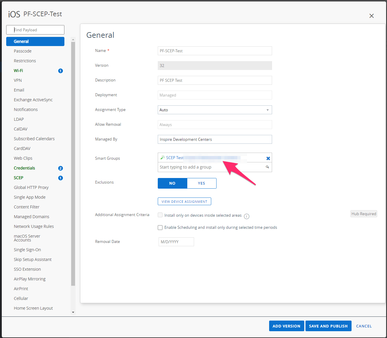
23. MFA Integration
This section provides quick overview for MFA integration with PacketFence.
23.1. Assumptions
Functional PacketFence server with configured Internal Source (e.g., Active Directory Source) associated to Connection Profile. RADIUS client performing PAP (e.g., VPN server or switch with CLI access using RADIUS).
23.2. Create the MFA Configuration
23.2.1. Akamai MFA
This section provides quick overview for configuring Akamai MFA in PacketFence.
23.2.2. Assumptions
You have Akamai MFA information required for PacketFence configuration.
Create the Multi-Factor configuration
Configure Akamai MFA from admin interface.
Go to "Configuration→Integration→Multi-Factor Authentication", click new MFA, select Akamai.
Complete form with following information:
Name: Define name
The App ID of the Akamai MFA: App ID provided by Akamai
The signing key of the Akamai MFA: Signing key provided by Akamai
The verify key of the Akamai MFA: Verify key provided by Akamai
The host of the Akamai MFA: Default: mfa.akamai.com
The callback URL to redirect back the user to PacketFence: This parameter is used when you trigger the MFA on the portal, once authenticate on Akamai Bind v2, it redirects to this specific URL to reach back the PacketFence’s portal. This value should be the FQDN of the portal with /mfa at the end (https://portal.acme.com/mfa)
RADIUS OTP Method: It is where you define which method you want to use in RADIUS (Explanation is covered in the next section)
Character separator: The character used to split the password and OTP when "Strip OTP" RADIUS method is selected.
Cache duration: The amount of time PacketFence will store the MFA information of the user (used for "Strip OTP" and "Second Password Field" since PacketFence deal with multiple RADIUS requests)
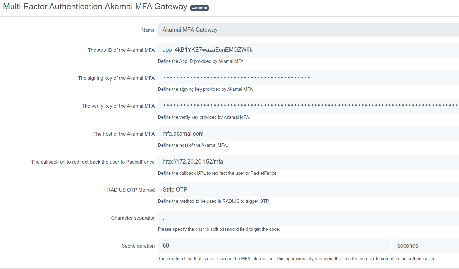
If MFA authentication fails, verify configuration and check RADIUS Audit Log to trace authentication flow.
23.2.3. TOTP MFA
This section has been created to give a quick overview on how to configure TOTP MFA in PacketFence.
23.2.4. Assumptions
You have a phone where you have an MFA application compatible with TOTP (Akamai MFA, Google Authenticator, Microsoft Authenticator, DUO).
Create the Multi-Factor configuration
In this section we will configure the OTP MFA from the admin interface.
Go in "Configuration → Integration→Multi-Factor Authentication" then click on new MFA and select TOTP.
In the form you have the following information to fill:
Name: Define a name
RADIUS OTP Method: It is where you define which method you want to use in RADIUS (Explanation are covered in the next section)
Character separator: The character used to split the password and OTP when "Strip OTP" RADIUS method is selected.
Cache duration: The amount of time PacketFence will store the MFA information of the user (used for "Strip OTP" and "Second Password Field" since PacketFence deal with multiple RADIUS requests)
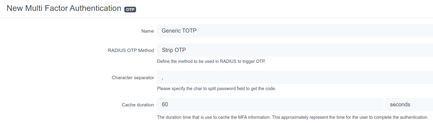
If MFA authentication fails, verify configuration and check RADIUS Audit Log to trace authentication flow.
23.2.5. Associate the source
MFA is triggered by authentication rule in Internal Source. Create rule with condition like "memberof equals cn=otp_user,dc=acme,dc=com" and assign Action:
"Trigger RADIUS MFA" for RADIUS triggering "Trigger Portal MFA" for Portal triggering.
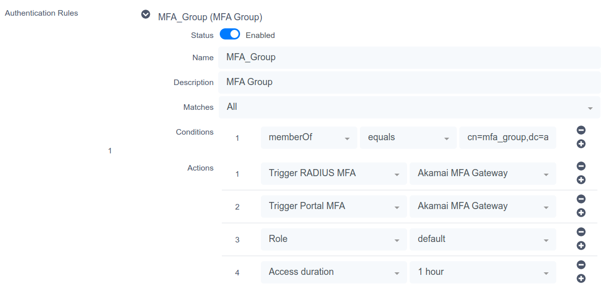
23.2.6. Portal Flow
Portal flow varies by MFA provider.
Akamai Bind v2
This section has been created to give a quick overview on how to configure Akamai Bind V2 in PacketFence.
Assumptions
You have all the Akamai MFA configuration made in PacketFence.
Connection Profile
First you need to have a connection profile that use the Internal Source where you defined a authentication rule that "Trigger Portal MFA" and also use the "Default portal policy" Root Portal Module (There is already the MFA policy defined in it).
Akamai Bind V2 portal
Once you are able to hit the portal and register with your credentials, the portal will forward you to the Akamai Bind V2 interface. From this page you will be able to onboard your device and also trigger any type of MFA. Once done and authenticated, Akamai Bind V2 portal will forward you back to PacketFence’s portal and will grant you the access.
Note: Before using Akamai MFA in the RADIUS flow, you need to onboard your device and it is a way to do it in PacketFence.
TOTP
This section has been created to give a quick overview on how to configure TOTP in PacketFence.
Assumptions
You have all the TOTP MFA configuration made in PacketFence.
Connection Profile
First you need to have a connection profile that use the Internal Source where you defined a authentication rule that "Trigger Portal MFA" and also use the "Default portal policy" Root Portal Module (There is already the MFA policy defined in it).
PacketFence Portal
Once you are able to hit the portal and register with your credentials, the portal will show you a QRcode you will need to scan with your device (Akamai / Google / Microsoft / DUO Authenticator per example). This will configure an account where you will be able to see "username.packetfence" and the OTP PIN code.
With that, you will be able to use this OTP on the portal to register your device.
Note: Before using OTP MFA in the RADIUS flow, you need to onboard your device on the portal.
23.2.7. RADIUS Flow
RADIUS flow depends on MFA provider features and RADIUS client capabilities.
Simple RADIUS client
In this use case only the username and password is sent in the RADIUS request, the only method available is the "push" notification. Once the user authenticated, a push notification will be sent on his phone and the user will have to validate in order to be granted.
Simple RADIUS client with password,<code>
In this user scenario the username and password is sent but the password can be splitted with a special character to obtain the code.
OTP code (123456):
OTP code from device (changes every 30s).
push code (push):
The code can be "push" to use the default phone or "pushx" (x represent the telephone index in the list if you have multiples one), push1 will trigger a push on the first phone, push2 on the second one. The user needs to validate on his phone in order to grant the access.
sms code (sms):
The code can be "sms" to use the default phone or "smsx" (x represent the telephone index in the list if you have multiples one), sms1 will trigger a push on the first phone, sms2 on the second one. The RADIUS request will be rejected and the RADIUS client will prompt again for the credentials.
Once the user receives the code by SMS he will need to reauthenticate with his username and password and append the SMS code. (like password,smscode)
phone code (phone):
The code can be "phone" to use the default phone or "phonex" (x represent the telephone index in the list if you have multiples one), phone1 will trigger a push on the first phone, phone2 on the second one. The RADIUS request will be rejected and the RADIUS client will prompt again for the credentials.
Once the user receives the code by phone call he will need to reauthenticate with his username and password and append the code. (like password,smscode)
Simple RADIUS client with 2nd password
In this user scenario the VPN client presents a login page with one username, password and a second password field. In this 2nd password field you can set multiples things like:
OTP code (123456):
OTP code from device (changes every 30s).
push code (push):
The code can be "push" to use the default phone or "pushx" (x represent the telephone index in the list if you have multiples one), push1 will trigger a push on the first phone, push2 on the second one. The user needs to validate on his phone in order to grant the access.
sms code (sms):
The code can be "sms" to use the default phone or "smsx" (x represent the telephone index in the list if you have multiples one), sms1 will trigger a push on the first phone, sms2 on the second one. The RADIUS request will be rejected and the RADIUS client will prompt again for the credentials.
Once the user receives the code by SMS he will need to reauthenticate with his username and password and set the code received by SMS in the 2nd password field.
phone code (phone):
The code can be "phone" to use the default phone or "phonex" (x represent the telephone index in the list if you have multiples one), phone1 will trigger a push on the first phone, phone2 on the second one. The RADIUS request will be rejected and the RADIUS client will prompt again for the credentials.
Once the user receives the code by phone call he will need to reauthenticate with his username and password and set the code received by phone in the 2nd password field.
24. Best Practices
24.1. IPTables
PacketFence manages IPTables entirely. For custom rules, create entries in
/usr/local/pf/conf/iptables-custom.conf.inc or modify
/usr/local/pf/conf/iptables.conf.tt. Default template works for most users.
More information available in Advanced topics → Iptables.
24.2. Log Rotations
PacketFence generates many log entries in large production environments. Use
logrotate for periodic log rotation. A working logrotate script is provided in
/etc/logrotate.d/ with daily rotation and compressed old logs. Added during
PacketFence installation.
24.3. Large Registration Network
Inline or VLAN enforcement in large environments may cause ARP table overflows
when many devices are on the same layer 2 segment. Symptoms include DHCP not
assigning IPs properly or failed pings in registration/quarantine VLANs. Check
dmesg log for Neighbour table overflow messages.
Mitigate by tweaking kernel settings. Enlarge ARP cache table by changing these sysctl.conf values:
net.ipv4.neigh.default.gc_thresh1 = 2048net.ipv4.neigh.default.gc_thresh2 = 4096net.ipv4.neigh.default.gc_thresh3 = 8192
Enable changes as root:
# sysctl -p
Layer 2 garbage collection starts at 2048 MAC addresses, with aggressive collection at 8192. This should suffice for most deployments - increase if needed (uses more kernel memory). Alternative solution: increase layer 2 network segmentation.
24.4. Active Directory fail-over
PacketFence authentication and authorization layers use 2 components for Active Directory 802.1x connections. Authentication: winbindd performs NTLM authentication for EAP-PEAP MSCHAPv2. Authorization: LDAP connections compute user roles. When using the captive portal or 802.1x authentication that doesn’t rely on NTLM authentication (EAP-TLS, EAP-TTLS, etc), then only LDAP is used.
When using multiple Active Directory servers, apply the following set of best practices to the installation so that PacketFence is able to efficiently detect a failure of one AD server and switch to the next one. This is even more important when the PacketFence deployment points to Active Directory servers located in 2 different availability zones (i.e. 2 different datacenters).
24.4.1. Authentication layer
To ensure the authentication layer will be able to fail-over efficiently, ensure that the 'Sticky DC' parameter of the domain configuration is set to *. Additionally, specify more than one DNS servers in that configuration. When using more than one availability zone, alternate the order of the servers. For example, when using the following DNS servers in the first availability zone: 10.0.1.100,10.0.1.101 and the following in the second availability zone: 10.0.2.100,10.0.2.101, the DNS servers list should be: 10.0.1.100,10.0.2.100,10.0.1.101,10.0.2.101 which will ensure the second DNS server to be queried is part of a different availability zone than the first one when winbindd queries DNS to find an available Active Directory domain controller.
Additional safety using monit
Some versions of samba/winbindd may not failover correctly when one of the DC fails, even with the best practices above. For this reason, it is suggested to enable monit on the installation. This will automatically activate an additional check that will restart winbindd if authentication fails to the current DC. Upon restart, a new DC will be found and authentication will resume. To enable this mecanism, enable monit as described in this section of the document and it be added automatically.
24.4.2. Authorization layer
The authorization layer of PacketFence uses the DNS servers setup on the operating system to resolve names. With that in mind, ensure that the servers in /etc/resolv.conf allow for proper fail-over should one of them fail. Similarly to the authentication layer, alternate the order of the servers based on the different availability zones. Also configure aggressive settings for fail-over to the next DNS server. For example, when using the following DNS servers in the first availability zone: 10.0.1.100,10.0.1.101 and the following in the second availability zone: 10.0.2.100,10.0.2.101, the resulting /etc/resolv.conf should be:
search example.comoptions timeout:1options retries:1nameserver 10.0.1.100nameserver 10.0.2.100nameserver 10.0.1.101nameserver 10.0.2.101
Once the DNS servers of the OS are setup to fail-over efficiently, review the configuration of the different Active Directory sources in PacketFence (Configuration → Policies and Access Control → Authentication Sources). In these sources, ensure that either a DNS name that resolves to multiple servers of the Active Directory domain is used or that multiple IP addresses are specified to connect. When uncertain about the robustness of the DNS layer, use multiple IP addresses.
25. Performance Optimizations
25.1. Multi Machine Account Support
PacketFence 14.1+ includes ntlm-auth-api multi-process support for NTLM requests. Previously, single machine account creation meant new NTLM auth requests waited for completion of previous requests. Single thread model slows performance in heavy load scenarios like large enterprises with extensive Windows AD databases and devices.
Multiple machine accounts can now be created, each registered with a dedicated process when NTLM auth API starts.
Enable by setting additional_machine_accounts to non-zero value. Machine
accounts will be created based on the previous machine account name.
The name pattern of additional machine account is:
"base_machine_account_name"-N, N will be 0..9
Example: Previous machine account NODE-PF with additional_machine_accounts set
to 2 creates NODE-PF-0 and NODE-PF-1 in Windows AD.
25.1.1. How does this work
PacketFence regenerates config file, determines required sub-processes for machine accounts, then gunicorn master process launches sub-processes to handle requests. Each sub-process uses dedicated machine account for authentication.
25.1.2. Limitations
-
Maximum 10 additional machine accounts per domain.
-
Machine account name cannot exceed 12 characters for
additional_machine_accounts. -
Using %h as machine account name requires parsed %h value under 12 characters.
25.1.3. Benchmarks and suggested settings
Benchmark results for reference: All the tests are done on VMs by ESXi 7.0 hosted on a SuperMicro server with 1 CPU of Intel D2123-IT (4C8T @2.2G), 128 G DDR4 RDIMM.
we are testing this using ab (apache benchmark) to directly test against NTLM auth API with:
-
2 additional machine accounts is added (total 3)
-
The PacketFence is hosted on a 4 vCPU 32 Gig VM on ESXi.
-
The Windows AD is hosted on a 2 vCPU 8 Gig VM on ESXi in the same local network with PacketFence.
ab -n 20000 -c 1 -p ~/eapol_test/payload.admin-akam.json -T 'application/json' http://127.0.0.1:5002/ntlm/authRequests per second: 448.22 [#/sec] (mean)Time per request: 2.231 [ms] (mean)Time per request: 2.231 [ms] (mean, across all concurrent requests)ab -n 20000 -c 2 -p ~/eapol_test/payload.admin-akam.json -T 'application/json' http://127.0.0.1:5002/ntlm/authRequests per second: 721.03 [#/sec] (mean)Time per request: 2.774 [ms] (mean)Time per request: 1.387 [ms] (mean, across all concurrent requests)ab -n 20000 -c 3 -p ~/eapol_test/payload.admin-akam.json -T 'application/json' http://127.0.0.1:5002/ntlm/authRequests per second: 932.21 [#/sec] (mean)Time per request: 3.218 [ms] (mean)Time per request: 1.073 [ms] (mean, across all concurrent requests)
Based on the test results, with a single machine account created on Windows AD, the backend API is possible to handle around 400 requests/s, with 3 machine accounts, the capacity will raise up to around 1000 req/s, which is a quite busy and heavy-load case.
We suggest creating no more than 5 additional machine accounts (6 total) to maximize the performance as well as keeping the Windows Event log clean and easy for debugging.
For low worker loads cases, 1 additional machine account is recommended - just to avoid jitter when the master process terminates the old process after 10k requests and re-spawn a new one.
25.2. NT Key Caching
Using NTLM authentication against an Active Directory for 802.1X EAP-PEAP connections can become a bottleneck when handling dozens of authentications per second. It is possible for PacketFence to cache NT keys in order to reduce external NTLM authentications. The NT key cache temporarily stores the NT session key for all connected devices, not the password or NT hashes.
When NT key caching is enabled, PacketFence will perform a transitive login with the Domain Controller, and cache the NT key of all connected devices that have successfully authenticated. Subsequent authentications will skip the transitive login with the Domain Controller and use the cached NT key. Wrong password and old password attempts are counted and cached to prevent the user account from being locked out from the Domain Controller.
25.2.1. PacketFence Configuration
Create Domain
To Enable NT key caching, create a valid Domain config entry in Configuration → Policies and Access Control → Domains → Active Directory Domains
In the NT Key cache tab,
- Enable NT Key cache.
- Specify a cache expiration time. Ranges from 60 to 86400. Default is 12000 (in seconds).
-
Fill in the Windows Group Policy Settings
- Account Lockout Threshold
- Reset Account Lockout Counter After
- Account Lockout Duration
- Old Password Allowed Period
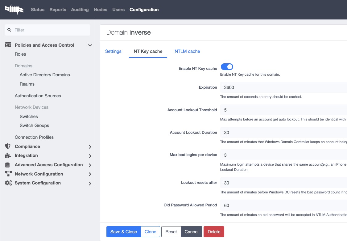
25.2.2. Restart NTLM Auth API
Restart the PacketFence NTLM Auth API to commit the changes.
systemctl restart packetfence-ntlm-auth-api
Windows Account Policies
Those settings can be found on the Windows Domain Controller by the following steps:
Go to Start menu → Administrative Tools → Group Policy Management.
In the console tree, expand Forest → Domains → Domain Name → Group Policy Objects → Default Domain Policy
In the right panel, navigate to Settings page, You will have these parameters in Policies → Windows Settings → Security Settings → Account Policies, Account lockout policies
For Old Password Allowed Period, There’s no group policy settings. The default value is 60 (in minutes). It can be changed using the following guide:
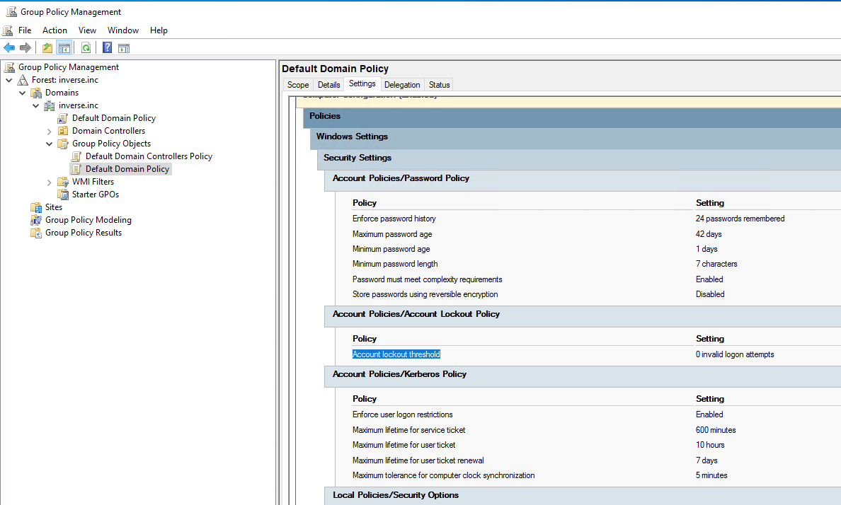
Create PacketFence User
Create a dedicated user that receives Windows Events from Domain Controller and reports the events to NT Key caching service:
- In the PacketFence Admin UI Users section, create a new local user with a unique username and a strong password. Remember these for Config Windows Event Notifier
- Change Access Level to Windows Event Receiver NTLM
25.2.3. Active Directory Configuration
Report the account Account Password Change, Account Password Reset (and optionally User Account Unlock) to PacketFence in order to help NT Key cache invalidate cache entries accurately.
Windows Event Notifier Configuration
Windows Event Notifier is a powershell script used to filter, analyze and report account management events to PacketFence.
Events include: * Account password change (Windows Event ID: 4723): mandatory for NT key cache * Account password reset (Windows Event ID: 4724): mandatory for NT key cache * User account unlock (Windows Event ID: 4767): optional, recommended - when disabled a user lock state is cached ⇐ 60s after unlock from Domain Controller
Preparation
Copy the powershell script and replace:
* Copy /usr/local/pf/addons/AD/password_change_notifier.ps1 to each Domain Controller that requires NT Key caching.
* Change $base_url and replace #PACKETFENCE_IP with the IP address of the PacketFence server.
* Enter $username and password from Create PacketFence User above.
* Enter $domainID from Create Domain above.
Config Scheduled Tasks
- Open Windows Task Scheduler and in the left-panel expand Event Viewer Tasks, on the right-panel, right-click on the blank area and select Create new task….
- In the popup window, Name the task and in Security options select Run whether user is logged on or not.
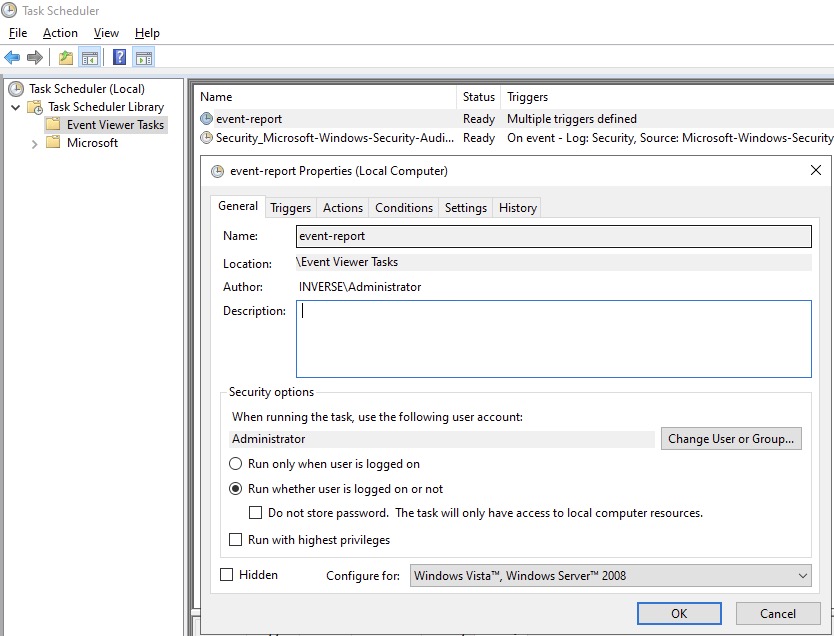
- Click on Trigger tab, then click New….
- In the popup window, for Begin the task select On an event, for Log select Security, for Event ID type in 4723, click "OK".
- Repeat these steps to add event trigger(s) for the Account Password Reset and optionally User Account Unlock events.
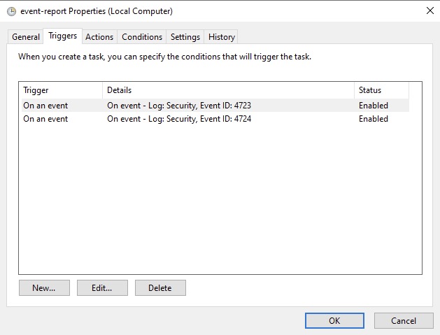
-
Click on Action tab, for Action select Start a program, in Program/script type the full path to powershell.exe (usually
C:\Windows\System32\WindowsPowerShell\v1.0\powershell.exe). -
In Add arguments type the full path to the powershell script (eg:
C:\Users\Administrator\Desktop\event-notifier.ps1). -
In Start in type the working directory (eg:
C:\Users\Administrator\Desktop).
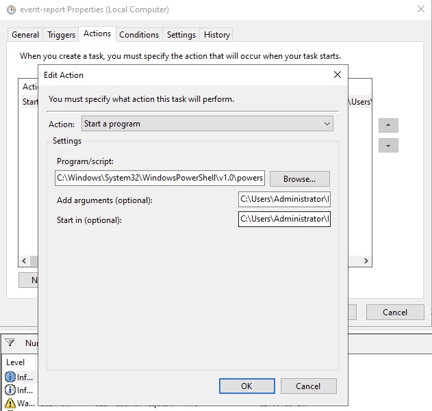
- Click "OK" to save the changes, Enter the Administrator password.
or
- Open Windows Event Viewer and click an event with EventID of 4723 (password change) or 4724 (password reset).
- Repeat the following steps for each Event ID.
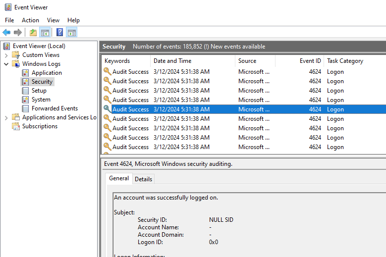
-
Select Attach tasks to this event in the right panel, then choose Launch a program for action option, fill in the
powershell REAL_ABSOLUTE_PATH_OF_THE_NOTIFIER_SCRIPT, click "Save". - Run the script with Administrator Privilege otherwise it will fail to read windows events.
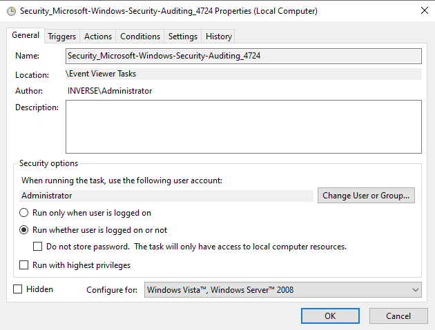
- After the task is saved it can be modified in Windows Task Scheduler.
Test Password Change
Manually reset a user password in Active Directory Users and Computers and
check to see if PacketFence received the event. The JSON entry in the chi_cache
value should contain dirty: 1. If PacketFence fails to receive the Event,
check the logs in the working directory from Config Scheduled Tasks above for
more information.
On the PacketFence server, use the cache query below and replace the [domainID] with the Domain ID from Create Domain above, and the [username] of the account user.
mysql pfmysql> SELECT value from chi_cache WHERE key='nt_key_cache:[domainID]:[username]';
25.3. NTLM Authentication Caching
When using NTLM authentication against an Active Directory for 802.1X EAP-PEAP connections, this can become a bottleneck when handling dozens of authentications per seconds.
To overcome this limitation, it is possible to use a Redis driven cache inside PacketFence to reduce the amount of authentications requiring an external NTLM authentication call. Should a user be in the cache, PacketFence will attempt to compare the 802.1X credentials with those. In the event that the validation fails, a call to ntlm_auth is made. In the event of a cache miss, an ntlm_auth call is made as well. This ensures that even if a user changes his password, his new password is immediately valid for 802.1X EAP-PEAP connections even if the cache contains the outdated entry.
25.3.1. PacketFence Configuration
First of all, you will need to enable the NTLM caching globally by enabling
'NTLM Redis cache' in Configuration → System Configuration → Radius →
General. You then need to restart radiusd-auth service.
Once that is done, you need to configure PacketFence to start caching the credentials. In order to do so, go in Configuration → Policies and Access Control → Domains → Active Directory Domains and select the domain you want to cache the credentials for.
Next, go in the NTLM cache tab and:
- Enable 'NTLM cache'
- Select the Active Directory authentication source that is tied to this domain.
- Adjust the 'Expiration'
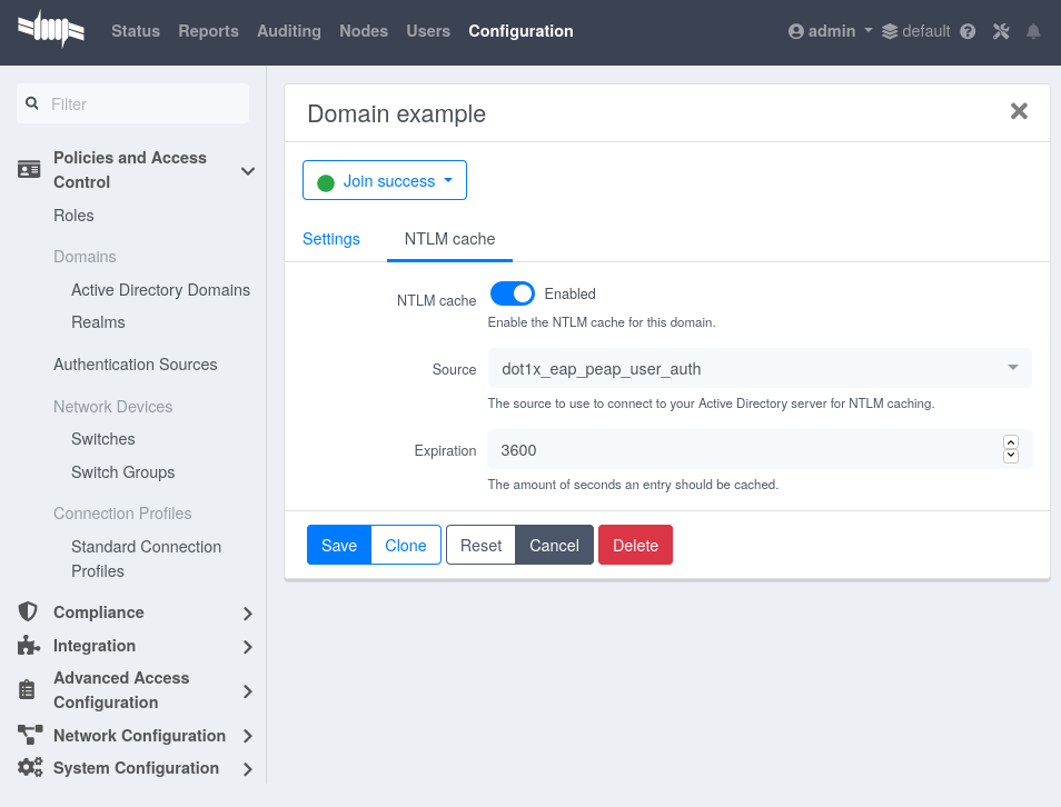
Once done, click on Save to commit the changes.
After that, you will need to enable the redis_ntlm_cache service which is used
by PacketFence to store the cached credentials. In order to do so, go in
Configuration → System Configuration → Main Configuration → Services and
enable 'redis_ntlm_cache' and save the changes.
Next, start the service via pfcmd:
/usr/local/pf/bin/pfcmd service redis_ntlm_cache start
25.3.2. Active Directory configuration
In order for PacketFence to be able to fetch the NTLM credentials from the Active Directory, it will need a user who has replication rights. The user to which you have to grant the rights, is the one that is configured in the authentication source that was associated in the 'NTLM cache' section of the domain.
Please refer to the following Microsoft KB entry to configure the replication rights (Replicating Directory Changes and Replicating Directory Changes All): https://support.microsoft.com/en-us/kb/303972
25.4. SNMP Traps Limit
PacketFence mainly rely on SNMP traps to communicate with equipment. Due to the fact that traps coming in from approved (configured) devices are all processed by the daemon, it is possible for someone who want to generate a certain load on the PacketFence server to force the generation of non-legitimate SNMP traps or a switch can randomly generate a high quantity of traps sent to PacketFence for an unknown reason.
Because of that, it is possible to limit the number of SNMP traps coming in from a single switch port and take action if that limit is reached. For example, if over 100 traps are received by PacketFence from the same switch port in a minute, the switch port will be shut and a notification email will be sent.
Here’s the default config for the SNMP traps limit feature. As you can see, by
default, PacketFence will log the abnormal activity after 100 traps from the
same switch port in a minute. These configurations are in the conf/pf.conf
file:
[snmp_traps]trap_limit = enabledtrap_limit_threshold = 100trap_limit_action =
Alternatively, you can configure these parameters from the admin interface, in the Configuration → Network Configuration → SNMP section.
25.5. MariaDB optimizations
25.5.1. Tuning MariaDB
If the PacketFence system is acting very slow, this could be due to the MariaDB configuration. You should do the following to tune performance:
Check the system load
# uptime11:36:37 up 235 days, 1:21, 1 user, load average: 1.25, 1.05, 0.79
Check iostat and CPU
# iostat 5avg-cpu: %user %nice %sys %iowait %idle0.60 0.00 3.20 20.20 76.00Device: tps Blk_read/s Blk_wrtn/s Blk_read Blk_wrtncciss/c0d0 32.40 0.00 1560.00 0 7800avg-cpu: %user %nice %sys %iowait %idle0.60 0.00 2.20 9.20 88.00Device: tps Blk_read/s Blk_wrtn/s Blk_read Blk_wrtncciss/c0d0 7.80 0.00 73.60 0 368avg-cpu: %user %nice %sys %iowait %idle0.60 0.00 1.80 23.80 73.80Device: tps Blk_read/s Blk_wrtn/s Blk_read Blk_wrtncciss/c0d0 31.40 0.00 1427.20 0 7136avg-cpu: %user %nice %sys %iowait %idle0.60 0.00 2.40 18.16 78.84Device: tps Blk_read/s Blk_wrtn/s Blk_read Blk_wrtncciss/c0d0 27.94 0.00 1173.65 0 5880
As you can see, the load-average is 1.25 and iowait is peaking at 20% - this is not good. If the iowait is low but the MariaDB is taking over 50% CPU this is also not good. Check the MariaDB install for the following variables:
MariaDB> show variables;| innodb_additional_mem_pool_size | 1048576 || innodb_autoextend_increment | 8 || innodb_buffer_pool_awe_mem_mb | 0 || innodb_buffer_pool_size | 8388608 |
PacketFence relies heavily on InnoDB, so you should increase the buffer_pool
size from the default values.
Go in the admin interface , in Configuration → System Configuration → Database → Advanced and raise the value of InnoDB buffer pool size.
Then restart packetfence-mariadb
# systemctl restart packetfence-mariadb
Wait 10 minutes re-check iostat and CPU
# uptime12:01:58 up 235 days, 1:46, 1 user, load average: 0.15, 0.39, 0.52# iostat 5Device: tps Blk_read/s Blk_wrtn/s Blk_read Blk_wrtncciss/c0d0 8.00 0.00 75.20 0 376avg-cpu: %user %nice %sys %iowait %idle0.60 0.00 2.99 13.37 83.03Device: tps Blk_read/s Blk_wrtn/s Blk_read Blk_wrtncciss/c0d0 14.97 0.00 432.73 0 2168avg-cpu: %user %nice %sys %iowait %idle0.20 0.00 2.60 6.60 90.60Device: tps Blk_read/s Blk_wrtn/s Blk_read Blk_wrtncciss/c0d0 4.80 0.00 48.00 0 240
25.5.2. Avoid "Too many connections" problems
In a wireless context, there tends to be a lot of connections made to the
database by our freeradius module. The default MariaDB value tend to be low
(100) so we encourage you to increase that value to at least 300. See
https://dev.mysql.com/doc/refman/5.0/en/too-many-connections.html for details.
25.5.3. Avoid "Host <hostname> is blocked" problems
In a wireless context, there tend to be a lot of connections made to the database by our freeradius module. When the server is loaded, these connection attempts can timeout. If a connection times out during connection, MariaDB will consider this a connection error and after 10 of these (by default) he will lock the host out with a:
Host 'host_name' is blocked because of many connection errors. Unblock with'mysqladmin flush-hosts'
This will grind PacketFence to a halt so you want to avoid that at all cost. One way to do so is to increase the number of maximum connections (see above), to periodically flush hosts or to allow more connection errors. See https://dev.mysql.com/doc/refman/5.0/en/blocked-host.html for details.
25.5.4. Using MariaDB-backup
When dealing with a large database, the database backup and maintenance script
(/usr/local/pf/addons/exportable-backup.sh) which uses mysqldump may create a
long lock on the database which may cause service to hang.
This is fixed easily by using MariaDB-backup which can complete a full database backup without locking the tables.
yum install MariaDB-backup --enablerepo=packetfence
apt install mariadb-backup
apt install mariadb-backup-10.2
Once this is done, grant the proper rights to the pf user (or the one you configured in pf.conf):
# mysql -u root -pMariaDB> GRANT PROCESS, RELOAD, LOCK TABLES, REPLICATION CLIENT ON *.* TO 'pf'@'localhost';MariaDB> FLUSH PRIVILEGES;
Next, run the maintenance script /usr/local/pf/addons/exportable-backup.sh and ensure that the following line is part of the output:
Exportable backup is done
If the backup fails, check /usr/local/pf/logs/innobackup.log for details and refer to the MariaDB-backup documentation for troubleshooting.
25.7. Troubleshooting
This section will address specific problems and known solutions.
25.7.1. "Internet Explorer cannot display the webpage"
Problem: Internet Explorer 8-10 may raise an "Internet Explorer cannot display the webpage" error while attempting to access PacketFence admin interface because TLSv1.2 is not activated but required since PacketFence 7.
Solution:
-
PacketFence admin interface is not started:
# cd /usr/local/pf# bin/pfcmd service httpd.admin start
- It is strongly advised to update the browser to Internet Explorer 11 or download an alternative.
-
TLSv1.2 needs to be activated manually in Internet Explorer 8-10.
Within Internet Explorer: click `Tools -> Internet Options -> Advanced` and make sure that TLS v1.2 is enabled under the security section. Retry.
26. Advanced Network Topics
26.1. Floating Network Devices
PacketFence supports floating network devices. A Floating network device is a device for which PacketFence has a different behavior compared to a non-floating (regular) network device. This functionality was originally added to support mobile Access Points.
A regular device is placed in the VLAN corresponding to its status (Registration, Isolation or Production VLAN) and is authorized on the port (port-security). This is not managed the same way as a floating network device.
When a floating network device is connected, PacketFence will let/allow all the MAC addresses are connected to this device or appear on the port. If necessary the port is configured as multi-vlan (trunk) the PVID is set and VLANs are tagged on the port.
When a floating network device is disconnected, PacketFence will reconfigure the port to what it was before the device connected.
26.1.1. How it works
Configuration:
- floating network devices have to be identified using their MAC address.
- linkup/linkdown traps are not enabled on the switches, only port-security traps are enabled.
configuration is changed with:
- disable port-security
- set the PVID
- eventually set the port as multi-vlan (trunk) and set the tagged VLANs
- enable linkdown traps
was connected, the port configuration is changed with:
- enable port-security
- disable linkdown traps
26.1.2. Identification
Each floating network device has to be identified. There are two ways to do this:
-
by editing
/usr/local/pf/conf/floating_network_device.conf - through the admin interface, in Configuration → Network Configuration → Floating Device
Available settings:
- MAC Address
-
MAC address of the floating device.
- IP Address
-
IP address of the floating device (not required, informational only).
- trunkPort
-
Should the port be configured as a multi-vlan port (yes/no)?
- pvid
-
Port VLAN.
- taggedVlan
-
Comma separated list of VLANs. If the port is a multi-vlan, these are the VLANs that are tagged on the port.
26.2. Production DHCP access
MAC addresses need to be mapped to IP addresses in order to perform access control.
To have the ability to isolate a node or to have IP information about a node within a network or VLAN, one of the following techniques must be used.
26.2.1. IP Helpers
If IP-helpers for your production DHCP in your production VLANs are already being used then this approach is the simplest to setup and works the best.
Add PacketFence’s management IP address as the last ip helper-address in your
network equipment. PacketFence will receive a copy of all DHCP requests for that
VLAN and will record the IP addresses that were leased to each device using the
pfdhcplistener daemon.
No DHCP Server should be listening on the interface where these requests are being sent, otherwise PacketFence would pointlessly reply to all DHCP requests.
26.2.2. Copy of the DHCP traffic
To copy all the DHCP Traffic from a dedicated physical interface of the
PacketFence server run pfdhcplistener on the desired interface. This will
properly configure the switch in order to perform port mirroring (network span)
and sets the proper interface parameters to the operating system and in
/usr/local/pf/conf/pf.conf.
/etc/sysconfig/network-scripts/ifcfg-eth2:
DEVICE=eth2ONBOOT=yesBOOTPROTO=none
Add to /usr/local/pf/conf/pf.conf:
[interface eth2]mask=255.255.255.0type=dhcp-listenergateway=192.168.1.5ip=192.168.1.1
Restart PacketFence to apply the changes.
26.2.3. Interface in every VLAN
Because DHCP traffic is broadcast traffic, an alternative for small networks
with few local VLANs is to put a VLAN interface for every VLAN on the
PacketFence server and have a pfdhcplistener listen on that VLAN interface.
On the network side ensure that the VLAN reaches from your client to the DHCP infrastructure to the PacketFence server.
First configure an operating system VLAN interface in PacketFence like the
example below /etc/sysconfig/network-scripts/ifcfg-eth0.1010:
# Engineering VLANDEVICE=eth0.1010ONBOOT=yesBOOTPROTO=staticIPADDR=10.0.101.4NETMASK=255.255.255.0VLAN=yes
Then specify type=dhcp-listener in /usr/local/pf/conf/pf.conf within the
VLANs using DHCP:
[interface eth0.1010]mask=255.255.255.0type=dhcp-listenergateway=10.0.101.1ip=10.0.101.4
Repeat the above steps for all production VLANs then restart PacketFence to apply the changes.
26.3. Routed Networks
PacketFence will need to be configured if the Isolation and Registration networks are not reachable locally (at layer 2) on the network, but instead routed to the PacketFence server. PacketFence is able to provide DHCP and DNS in these routed networks.
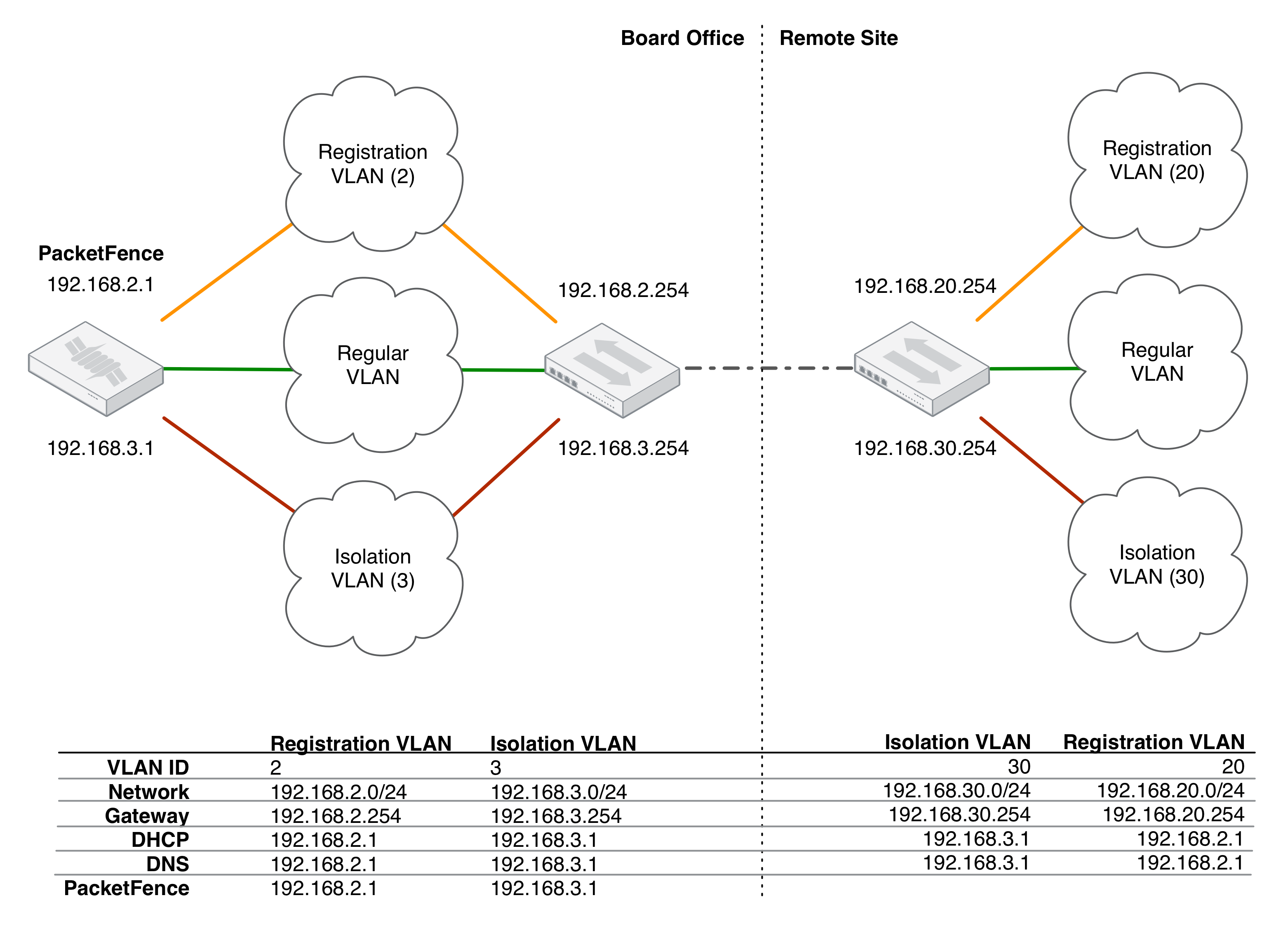
For dhcpd, ensure the clients DHCP requests are being forwarded correctly (IP Helpers in the remote routers) to the PacketFence server.
Considering the network architecture illustrated above,
/usr/local/pf/conf/pf.conf will include the local Registration and
Isolation interfaces only.
[interface eth0.2]enforcement=vlanip=192.168.2.1type=internalmask=255.255.255.0
[interface eth0.3]enforcement=vlanip=192.168.3.1type=internalmask=255.255.255.0
dhcpd daemon only listens on the
'internal' interfaces, therefore the remote Registration and Isolation subnets
need to point their DHCP helper-address to those particular IP addresses.Provide the routed networks to PacketFence through the admin interface in
Configuration → Network Configuration → Networks or manually in
/usr/local/pf/conf/networks.conf.
Example /usr/local/pf/conf/networks.conf:
[192.168.2.0]netmask=255.255.255.0gateway=192.168.2.1next_hop=domain-name=registration.example.comdns=192.168.2.1dhcp_start=192.168.2.10dhcp_end=192.168.2.200dhcp_default_lease_time=300dhcp_max_lease_time=600type=vlan-registrationnamed=enableddhcpd=enabled
[192.168.3.0]netmask=255.255.255.0gateway=192.168.3.1next_hop=domain-name=isolation.example.comdns=192.168.3.1dhcp_start=192.168.3.10dhcp_end=192.168.3.200dhcp_default_lease_time=300dhcp_max_lease_time=600type=vlan-isolationnamed=enableddhcpd=enabled
[192.168.20.0]netmask=255.255.255.0gateway=192.168.20.254next_hop=192.168.2.254domain-name=registration.example.comdns=192.168.2.1dhcp_start=192.168.20.10dhcp_end=192.168.20.200dhcp_default_lease_time=300dhcp_max_lease_time=600type=vlan-registrationnamed=enableddhcpd=enabled
[192.168.30.0]netmask=255.255.255.0gateway=192.168.30.254next_hop=192.168.3.254domain-name=isolation.example.comdns=192.168.3.1dhcp_start=192.168.30.10dhcp_end=192.168.30.200dhcp_default_lease_time=300dhcp_max_lease_time=600type=vlan-isolationnamed=enableddhcpd=enabled
Restart packetfence-keepalived to apply the changes:
/usr/local/pf/bin/pfcmd service keepalived restart
DHCP clients on the Registration and Isolation networks receive the PacketFence server IP as their DNS server in their lease, then DNS responses are spoofed to force clients via the portal. However, clients could manually configure their DNS settings to escape the portal. To prevent this, apply an ACL on the access router nearest to the clients, permitting access only to the PacketFence server and local DHCP broadcast traffic.
Example for VLAN 20 remote Registration network:
ip access-list extended PF_REGISTRATIONpermit ip any host 192.168.2.1permit udp any any eq 67deny ip any any loginterface vlan 20ip address 192.168.20.254 255.255.255.0ip helper-address 192.168.2.1ip access-group PF_REGISTRATION in
If the edge switches support 'vlan-isolation' the ACL can also be applied there. This has the advantage of preventing machines in Isolation from attacking each other.
26.4. Network Devices Definition
Used only for VLAN enforcement. Inline enforcement can skip this section.
PacketFence needs to know which switches, access points or controllers it manages, their type and configuration. You can modify this configuration directly in /usr/local/pf/conf/switches.conf or from the admin interface in Configuration → Policies and Access Control → Switches (recommended).
/usr/local/pf/conf/switches.conf configuration file contains a default section including:- Default SNMP read/write communities for the switches
- Default working mode (see the note below about possible working modes)
- Switch IP/MAC/Range
- Switch vendor/type
- Switch uplink ports (trunks and non-managed IfIndex)
- per-switch re-definition of the VLANs (if required)
Reload the configuration to apply the changes:
/usr/local/pf/bin/pfcmd configreload
/usr/local/pf/conf/switches.conf. A different uplink list for each switch can be defined.26.4.1. Working modes
Switches utilize three different working modes:
- Testing
-
pfsetvlan writes in the log files what it would normally do, but no VLAN changes are performed.
- Registration
-
pfsetvlan automatically registers all MAC addresses seen on the switch ports, but no VLAN changes are performed.
- Production
-
pfsetvlan sends the SNMP writes to change the VLAN on the switch ports.
26.4.2. RADIUS
To set the RADIUS secret, set it from the Web Administrative GUI when adding a switch. Alternatively, edit the switch configuration file /usr/local/pf/conf/switches.conf and set the following parameters
radiusSecret = secretPassPhrase
26.4.3. SNMP v1, v2c and v3
SNMP is used to communicate with most switches. PacketFence also supports SNMPv3 which is used for bi-directional communication, from the switch to PacketFence and from PacketFence to the switch. SNMP usage is discouraged, as RADIUS should now be used. However, even if RADIUS is being used, some switches may also require SNMP configuration to work properly.
From PacketFence to a switch
Set the following parameters in the switch configuration file /usr/local/pf/conf/switches.conf:
SNMPVersion = 3SNMPEngineID = AA5ED139B81D4A328D18ACD1SNMPUserNameRead = readUserSNMPAuthProtocolRead = MD5SNMPAuthPasswordRead = authpwdreadSNMPPrivProtocolRead = AESSNMPPrivPasswordRead = privpwdreadSNMPUserNameWrite = writeUserSNMPAuthProtocolWrite = MD5SNMPAuthPasswordWrite = authpwdwriteSNMPPrivProtocolWrite = AESSNMPPrivPasswordWrite = privpwdwrite
From a switch to PacketFence
Set the following parameters in the switch configuration file /usr/local/pf/conf/switches.conf:
SNMPVersionTrap = 3SNMPUserNameTrap = readUserSNMPAuthProtocolTrap = MD5SNMPAuthPasswordTrap = authpwdreadSNMPPrivProtocolTrap = AESSNMPPrivPasswordTrap = privpwdread
Switch Configuration
Set the following switch configuration in order to enable SNMPv3 in both directions on a Cisco Switch.
snmp-server engineID local AA5ED139B81D4A328D18ACD1snmp-server group readGroup v3 privsnmp-server group writeGroup v3 priv read v1default write v1defaultsnmp-server user readUser readGroup v3 auth md5 authpwdread priv aes 128 privpwdreadsnmp-server user writeUser writeGroup v3 auth md5 authpwdwrite priv aes 128 privpwdwritesnmp-server enable traps port-securitysnmp-server enable traps port-security trap-rate 1snmp-server host 192.168.0.50 version 3 priv readUser port-security
Obtain the SNMPv3 engine identifier (SNMPEngineID) with show snmp engineid.
Test from a PacketFence server
The net-snmp package can test SNMPv3 communication with a switch:
snmpget -v3 -l authPriv -u readUser -a MD5 -A "authpwdread" \-x AES -X "privpwdread" IP_OF_YOUR_SWITCH sysName.0
26.4.4. Command-Line Interface: Telnet and SSH
cliUser and cliPwd provided grants privileged mode (except for Trapeze hardware).PacketFence can occasionally establish an interactive command-line session with a switch. This can be done using either Telnet or SSH. Edit the switch configuration file /usr/local/pf/conf/switches.conf and set the following parameters or :
cliTransport = SSH (or Telnet)cliUser = admincliPwd = admin_pwdcliEnablePwd =
This can also be configured with the admin interface in Configuration → Policies and Access Control → Switches.
26.4.5. Web Services Interface
PacketFence can occasionally establish a Web Services dialog with a switch. Edit the switch config file /usr/local/pf/conf/switches.conf and set the following parameters:
wsTransport = http (or https)wsUser = adminwsPwd = admin_pwd
This can also be configured with the admin interface in Configuration → Policies and Access Control → Switches.
26.4.6. Role-based Enforcement
Some network devices support the assignment of a specific set of rules (firewall or ACLs) to a user. These rules are more accurate in controlling what a user can or cannot do compared to VLAN, which has a larger overhead with network management. PacketFence can assign roles on devices with switches and WiFi controllers that support role-based assignment.
A special internal-role to external-role assignment must be configured in the switch configuration file /usr/local/pf/conf/switches.conf using the format <role_name>Role=<controller_role>. Provide the internal-role to external-role assignments on either the switch, or the parent switch group.
Example that returns the full-access role to the nodes categorized as admin or engineering and the role little-access to nodes categorized as sales:
adminRole=full-accessengineeringRole=full-accesssalesRole=little-access
This can also be configured with the admin interface in Configuration → Policies and Access Control → Switches.
26.4.7. VoIP Integration with CDP, LLDP and LLDP-MED
Cisco Discovery Protocol (CDP) is device-discovery protocol supported on all Cisco-manufactured equipment including routers, access servers, bridges, and switches. Using CDP, a device can advertise its existence to other devices and receive information about other devices on the same LAN or on the remote side of a WAN. CDP can determine if the connecting device is an IP Phone, and instruct the IP Phone to tag ethernet frames using the configured voice VLAN on the switchport.
Many other vendors support LLDP or LLDP-MED. Link Layer Discovery Protocol (LLDP) is a vendor-neutral Link Layer protocol in the Internet Protocol Suite used by network devices for advertising their identity, capabilities, and neighbors. Same as CDP, LLDP can instruct an IP Phone which VLAN ID is the voice VLAN.
26.4.8. VoIP and VLAN assignment
VLAN assignment techniques such as port-security, MAC authentication and 802.1X are supported.
Port-security
Using port-security, the VoIP device relies on CDP/LLDP to tag the ethernet frames using the configured voice VLAN on the switch port. Afterwards a security trap is sent from the voice VLAN so PacketFence can authorize the MAC address on the port. When the device connects another security trap is sent from the data VLAN. That way, 1 MAC address is authorized on the voice VLAN, and 1 on the access VLAN.
MAC Authentication and 802.1X
Cisco switches support a multi-domain configuration using Vendor-Specific Attributes (VSA), which allows one device on the VOICE domain and one device on the DATA domain. When the phone connects to the switch port, PacketFence will only respond with the proper VSA, no RADIUS tunneled attributes. CDP then instructs the phone to tag ethernet frames using the configured voice VLAN on the switch port. When a PC connects, the RADIUS server returns the tunneled attributes, and the switch will place the port in the provided access VLAN.
On other vendor hardware VoIP works using RADIUS VSAs. When an IP phone connects to a switch port, the proper VSA is returned to instruct the switch to allow tagged frames from this device. When a PC connects, PacketFence will return the standard RADIUS tunnel attributes to the switch, for the untagged VLAN.
26.4.9. What if CDP/LLDP feature is missing
If an IP phone does not support CDP or LLDP, DHCP can be used to provision the device with a voice VLAN. Some models require a specific DHCP option in order for the DHCP server to lease the device a voice VLAN ID. After rebooting the ethernet frames are tagged using the provided VLAN tag.
For this scenario to work, the Registration and Production DHCP servers must be configured to provide the DHCP option, there is a voice VLAN configured on the port, and IP Phones are auto-registered (On the first connection, the phone is assigned on the registration VLAN).
26.5. DHCP Option 82
PacketFence is able to locate a device on the network even if the switch port is not managed by PacketFence.
All switches must be added and SNMP read (switch and PacketFence side) enabled in Configuration → Policies and Access Control → Network Devices → Switches.
Enable DHCP option 82 in Configuration → Network Configuration → Networks → Network. Once enabled, restart the pfdhcplistener and pfmon (or pfcron, if Packetfence version is >= 10.2) services. pfmon (or pfcron) queries all the switches via SNMP to maintain a map (MAC address → switch). pfdhcplistener parses DHCP Option 82 and uses the map to resolve the MAC to the switch while updating the locationlog of the device.
27. Additional Integration
27.1. DHCP Remote Sensor
The DHCP remote sensor consists of a lightweight binary installed on the production DHCP server to replicate all DHCP traffic (1-to-1) to the PacketFence server. This solution is more reliable than DHCP relaying since PacketFence receives a copy of all the DHCP traffic including broadcast traffic. Supported DHCP servers include Microsoft DHCP server and CentOS 6 and 7.
These sensors capture low-level packets on the DHCP server and forwards them to the PacketFence management interface.
27.1.1. Microsoft Remote Sensor
The PacketFence-Forwarder is an optimized version of the udp-reflector, which installs easily and only forwards DHCPREQUESTS and DHCPACK packets from the source to the destination as well optionally mirroring DNS traffic for integration with the Fingerbank Collector
Download the DHCP Forwarder installer.
This installs nPCAP, nssm, launches a configurator for the interface, IP and
port, saves the configuration, and finally installs and launches the
DHCP-Forwarder service.
When asked for a host IP and UDP port for DHCP mirroring provide the PacketFence management IP and 767 respectively.
Visit the PacketFence Forwarder project page.
27.1.2. Linux-based Sensor
First download the RPM on your DHCP server.
CentOS 6 and 7 servers
For CentOS 6 (x86_64):
wget http://inverse.ca/downloads/PacketFence/CentOS6/extra/x86_64/RPMS/udp-reflector-1.0-6.1.x86_64.rpm
For CentOS 7 (x86_64):
wget http://inverse.ca/downloads/PacketFence/CentOS7/extra/x86_64/RPMS/udp-reflector-1.0-6.1.x86_64.rpm
Install the sensor with rpm:
rpm -i udp-reflector-*.rpm
Compiling the sensor from source on a Linux system
First ensure the following packages are installed:
- libpcap
- libpcap-devel
- gcc-c++
Get the sensor source code:
mkdir -p ~/udp-reflector && cd ~/udp-reflectorwget http://inverse.ca/downloads/PacketFence/udp-reflector/udp_reflector.cppg++ udp_reflector.cpp -o /usr/local/bin/udp_reflector -lpcap
Configure the Sensor
Place the following line in /etc/rc.local
-
where
pcap0is the pcap interface where the DHCP server listens on. (List them usingudp_reflector -l) -
where
192.168.1.5is the management IP of the PacketFence server
/usr/local/bin/udp_reflector -s pcap0:67 -d 192.168.1.5:767 -b 25000 &
Start the sensor:
/usr/local/bin/udp_reflector -s pcap0:67 -d 192.168.1.5:767 -b 25000 &
All DHCP traffic is now reflected to the PacketFence server.
27.2. Active Directory Integration
27.2.1. Deleted Account
Create the script unreg_node_deleted_account.ps1 on the Windows Server with
the following content:
##########################################################################################Powershell script to unregister deleted Active Directory account based on theUserName.##########################################################################################Get-EventLog -LogName Security -InstanceId 4726 |Select ReplacementStrings,"Account name"|% {$url = "https://@IP_PACKETFENCE:9090/"$username = "admin" # Username for the webservices$password = "admin" # Password for the webservices[System.Net.ServicePointManager]::ServerCertificateValidationCallback = {$true}$command = '{"jsonrpc": "2.0", "method": "unreg_node_for_pid", "params": ["pid", "'+$_.ReplacementStrings[0]+'"]}'$bytes = [System.Text.Encoding]::ASCII.GetBytes($command)$web = [System.Net.WebRequest]::Create($url)$web.Method = "POST"$web.ContentLength = $bytes.Length$web.ContentType = "application/json-rpc"$web.Credentials = new-object System.Net.NetworkCredential($username, $password)$stream = $web.GetRequestStream()$stream.Write($bytes,0,$bytes.Length)$stream.close()$reader = New-Object System.IO.Streamreader -ArgumentList $web.GetResponse().GetResponseStream()$reader.ReadToEnd()$reader.Close()}
@IP_PACKETFENCE to the IP address of the PacketFence server
and change the $username and $password so they match the credentials
defined in the Web admin interface under
Configuration → Integration → Web Services.Create a scheduled task for an event ID
Start → Run → Taskschd.msc
Task Scheduler → Task Scheduler Library → Event Viewer Task → Create Task
General
Name: PacketFence-Unreg_node-for-deleted-accountCheck: Run whether user is logged on or notCheck: Run with highest privileges
Triggers → New
Begin on the task: On an eventLog: SecuritySource: Microsoft Windows security auditing.Event ID: 4726
Actions → New
Action: Start a programProgram/script: powershell.exeAdd arguments (optional): C:\scripts\unreg_node_deleted_account.ps1
Settings:
At the bottom, select in the list "Run a new instance in parallel" in order tounregister multiple nodes at the same time.
Validate with Ok and provide the account that will run this task (usually DOMAIN\Administrator).
27.2.2. Disabled Account
Preventing Authentication of Disabled Accounts via LDAP Filter
You can prevent disabled Active Directory accounts from authenticating through PacketFence by adding an LDAP filter that excludes accounts with the ACCOUNTDISABLE flag set.
In Active Directory, the userAccountControl attribute contains bitwise flags that indicate account properties. Bit 2 (0x2) corresponds to ACCOUNTDISABLE. The following LDAP filter uses the bitwise AND matching rule (1.2.840.113556.1.4.803) to check whether this bit is set, and excludes those accounts from search results:
(!(userAccountControl:1.2.840.113556.1.4.803:=2))
To configure this in PacketFence:
-
Go to Configuration → Policies and Access Control → Authentication Sources.
-
Edit your Active Directory authentication source.
-
In the Append search attributes LDAP filter field, paste the filter above.
-
Save the configuration.
With this filter in place, LDAP search filters generated for authentication lookups, such as username-based authentication and matching, will exclude disabled accounts and help prevent them from authenticating.
Rejecting Disabled Accounts in Authentication Rules
You can also check the userAccountControl attribute directly in authentication rule conditions using the has bit and not has bit operators. These operators perform a bitwise AND check against the attribute value, which is the correct way to test individual flags in a bitmask attribute like userAccountControl.
In Active Directory, bit 2 (0x2) of userAccountControl corresponds to ACCOUNTDISABLE: when this bit is set, the account is disabled. A rule that matches disabled accounts and assigns the REJECT role is therefore the correct way to block them.
To create a rule that rejects disabled accounts:
-
Go to Configuration → Policies and Access Control → Authentication Sources.
-
Edit your Active Directory authentication source and create a new authentication rule (place it above your other rules so it is evaluated first).
-
Add a condition:
userAccountControl→ has bit →2. -
In the rule actions, set Role to
REJECTand set an Access duration (for example,1 hour). -
Save the rule.
This rule matches any account that has the ACCOUNTDISABLE bit set (bit 2), regardless of what other flags are present in userAccountControl, and rejects the authentication.
userAccountControl value and are not suitable for bitmask attributes. Always use has bit or not has bit when checking individual flags.Unregistering Nodes When an Account is Disabled (Event-Based)
Create the script unreg_node_disabled_account.ps1 on the Windows Server with the following content:
###########################################################################################Powershell script to unregister disabled Active Directory account based on theUserName.###########################################################################################Get-EventLog -LogName Security -InstanceId 4725 |Select ReplacementStrings,"Account name"|% {$url = "https://@IP_PACKETFENCE:9090/"$username = "admin" # Username for the webservices$password = "admin" # Password for the webservices[System.Net.ServicePointManager]::ServerCertificateValidationCallback = {$true}$command = '{"jsonrpc": "2.0", "method": "unreg_node_for_pid", "params": ["pid", "'+$_.ReplacementStrings[0]+'"]}'$bytes = [System.Text.Encoding]::ASCII.GetBytes($command)$web = [System.Net.WebRequest]::Create($url)$web.Method = "POST"$web.ContentLength = $bytes.Length$web.ContentType = "application/json-rpc"$web.Credentials = new-object System.Net.NetworkCredential($username, $password)$stream = $web.GetRequestStream()$stream.Write($bytes,0,$bytes.Length)$stream.close()$reader = New-Object System.IO.Streamreader -ArgumentList $web.GetResponse().GetResponseStream()$reader.ReadToEnd()$reader.Close()}
@IP_PACKETFENCE to the IP address of the PacketFence server
and change the $username and $password so they match the credentials
defined in the Web admin interface under
Configuration → Integration → Web Services.Create a scheduled task for an event ID
Start → Run → Taskschd.msc
Task Scheduler → Task Scheduler Library → Event Viewer Task → Create Task
General
Name: PacketFence-Unreg_node-for-disabled-accountCheck: Run whether user is logged on or notCheck: Run with highest privileges
Triggers → New
Begin on the task: On an eventLog: SecuritySource: Microsoft Windows security auditing.Event ID: 4725
Actions → New
Action: Start a programProgram/script: powershell.exeAdd arguments (optional): C:\scripts\unreg_node_disabled_account.ps1
Settings:
At the bottom, select in the list "Run a new instance in parallel"
Validate with Ok and provide the account that will run this task (usually DOMAIN\Administrator).
27.2.3. Locked Account
Create the script unreg_node_locked_account.ps1 on the Windows Server with the following content:
##########################################################################################Powershell script to unregister locked Active Directory account based on theUserName.##########################################################################################Get-EventLog -LogName Security -InstanceId 4740 |Select ReplacementStrings,"Account name"|% {$url = "https://@IP_PACKETFENCE:9090/"$username = "admin" # Username for the webservices$password = "admin" # Password for the webservices[System.Net.ServicePointManager]::ServerCertificateValidationCallback = {$true}$command = '{"jsonrpc": "2.0", "method": "unreg_node_for_pid", "params": ["pid", "'+$_.ReplacementStrings[0]+'"]}'$bytes = [System.Text.Encoding]::ASCII.GetBytes($command)$web = [System.Net.WebRequest]::Create($url)$web.Method = "POST"$web.ContentLength = $bytes.Length$web.ContentType = "application/json-rpc"$web.Credentials = new-object System.Net.NetworkCredential($username, $password)$stream = $web.GetRequestStream()$stream.Write($bytes,0,$bytes.Length)$stream.close()$reader = New-Object System.IO.Streamreader -ArgumentList $web.GetResponse().GetResponseStream()$reader.ReadToEnd()$reader.Close()}
@IP_PACKETFENCE to the IP address of the PacketFence server
and change the $username and $password so they match the credentials
defined in the Web admin interface under
Configuration → Integration → Web Services.Create the scheduled task based on an event ID
Start → Run → Taskschd.msc
Task Scheduler → Task Scheduler Library → Event Viewer Task → Create Task
General
Name: PacketFence-Unreg_node-for-locked-accountCheck: Run whether user is logged on or notCheck: Run with highest privileges
Triggers → New
Begin on the task: On an eventLog: SecuritySource: Microsoft Windows security auditing.Event ID: 4740
Actions → New
Action: Start a programProgram/script: powershell.exeAdd arguments (optional): C:\scripts\unreg_node_locked_account.ps1
Settings:
At the bottom, select in the list "Run a new instance in parallel"
Validate with Ok and provide the account that will run this task (usually DOMAIN\Administrator).
27.3. Switch Login Access
PacketFence is able to provide an authentication and authorization service on port 1815 for granting command-line interface (CLI) access to switches. PacketFence currently supports Cisco switches which must be configured using the following guide: https://www.cisco.com/c/en/us/support/docs/security-vpn/remote-authentication-dial-user-service-radius/116291-configure-freeradius-00.html. From the PacketFence admin interface, configure an Admin Access role (Configuration → System Configuration → Admin Access) that contains the action 'Switches CLI - Read' or 'Switches CLI - Write' and assign this role to an internal user or with an Administration rule in an internal source.
Then enable CLI Access Enabled setting on the switch(s) to manage in Configuration → Network devices → Switches.
ALL administrative role allows the user to login into the switches. Change this role to ALL_PF_ONLY to allow the user all the necessary administrative roles except for switch login.27.4. Syslog forwarding
Syslog forwarding forwards PacketFence logs (all or specific log files) to a remote Syslog server using the Syslog protocol.
Configure this feature in Configuration → Integration → Syslog Forwarding
After adding a new Syslog server, perform the following commands:
systemctl restart rsyslog
Logs are retained on the PacketFence server and a copy is sent to the remote Syslog server(s).
27.5. Monit
monit manages and monitors processes, files, directories and filesystems on a Unix system. Monit conducts automatic maintenance and repair, and can execute meaningful causal-actions in error situations. E.g. Monit can start a process if it stops running, restart a process if it does not respond and stop a process if it uses too much resources.
For further reference the monit documentation is available at: https://mmonit.com/monit/documentation/monit.html
The monit configuration path is different between EL and Debian systems:
EL based systems:
-
MONIT_PATH=/etc/monit.d
Debian based systems:
-
MONIT_PATH=/etc/monit/conf.d
To simplify further documentation, $MONIT_PATH will be used as a reference to these paths herein.
Starting from PacketFence 11.1, the Monit configuration is directly managed by PacketFence.
To enable Monit, configure the following settings in Configuration → System Configuration → Main Configuration → Monit:
- Status: enabled
- Alert Email To: The email address(es) to send the alerts. If left empty, the default email addresses defined in Configuration → System Configuration → Main Configuration → Alerting will be used.
- Configuration: Enter the configurations for monit to use. If left empty, the defaults should be fine unless port-security enforcement or active/passive cluster is used.
- Mailserver: Specify the mailserver to use. This can only be used for unauthenticated relaying. If using localhost, ensure postfix is installed and properly configured. If left empty, the SMTP server settings in Configuration → System Configuration → Main Configuration → Alerting are used. Note that monit doesn’t support StartTLS so 'none' or 'ssl' must be configured for SMTP encryption in the alerting configuration. If StartTLS is required, configure postfix for relaying and use 'localhost' as the Mailserver in the monit configuration.
Restart the monit service:
systemctl restart monit
27.5.1. Monitoring scripts
Digitally signed scripts are included in the monit configuration which are fetched from https://inverse.ca/downloads/PacketFence/monitoring-scripts/v1/. These scripts will be updated and run at regular intervals to ensure the environment follows the best practices defined by Inverse and to email alerts of any important changes that may need to be performed.
Run manually to help with troubleshooting:
/usr/local/pf/addons/monit/monitoring-scripts/update.sh/usr/local/pf/addons/monit/monitoring-scripts/run-all.sh
Ignoring some checks
To ignore one of the checks that are being performed, add its script name in $MONIT_PATH/packetfence/local-ignores.
For example, to ignore the script that generated the following output add /usr/local/pf/var/monitoring-scripts/.check-epel.sh to $MONIT_PATH/packetfence/local-ignores:
------------------------------------------/usr/local/pf/var/monitoring-scripts/.check-epel.sh failedResult of /usr/local/pf/var/monitoring-scripts/.check-epel.shThe EPEL repository is enabled. This can cause disastrous issues by having thewrong versions of certain packages installed. It is recommended to disable itusing the following command: sed -i 's/enabled\s*=\s*1/enabled = 0/g'/etc/yum.repos.d/epel.repo------------------------------------------
Run some checks as root
Some scripts need to run as root but are disabled by default. To run these checks add the following in $MONIT_PATH/packetfence/local-vars:
export RUN_ROOT_SCRIPTS=1
27.5.2. Monit Summary
View the monit summary and ensure all services show status Running, Accessible, or Status ok. Any services that display a failed status will need to be investigated. Monit will process and display the services in the same order that they are listed. If the summary appears stuck, troubleshoot the next service in the list.
monit summary
27.6. FleetDM Integration
27.6.1. Background
PacketFence provides flexible osquery support, regular vulnerability checks, and policy compliance through FleetDM integration. From PacketFence v14.0, FleetDM can report policy violations and CVE vulnerabilities of managed nodes to PacketFence.
27.6.2. Install and Configure FleetDM
Follow FleetDM’s official best practices to deploy the FleetDM service:
- FleetDM official website: https://fleetdm.com/
- Documentation: https://fleetdm.com/docs/get-started/why-fleet
27.6.3. Configure PacketFence
- Check if the FleetDM Events Handler role exists. Navigate to Admin UI → Configuration → System Configuration → Admin Access and verify the role appears in the right panel. If the role exists, skip the next step.
- Create the role if missing. Click New admin role, set name to FleetDM Event Handler, Description to Receives FleetDM events, actions to FLEETDM_EVENTS_READ, then click Save.
- Create a user from Admin UI → Users → Create. Choose a Username (PID) and strong password, set Access Level to FleetDM Event Handler
27.6.4. Configure FleetDM API in PacketFence
- Navigate to Admin UI → Configuration → System Configuration → FleetDM to configure the FleetDM endpoint.
- Enter FleetDM login email and password OR FleetDM API Token, then click Save.
- Temporary API tokens: Login to FleetDM, click the user icon (top right), select My Account → Get API Token
- To create a permanent API Key in FleetDM, please refer to official documents: https://fleetdm.com/docs/using-fleet/fleetctl-cli?utm_medium=fleetui&utm_campaign=get-api-token#using-fleetctl-with-an-api-only-user
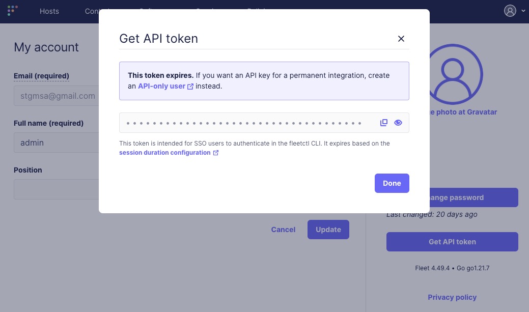
27.6.5. Configure FleetDM
Policy Violations
- Login to FleetDM admin Panel → Policies → Manage Automations.
- In the popup window, enable Policy automations enabled, workflow: Webhook.
-
For destination URL, fill in
https://USER:PASS@packetfence.fqdn:9999/api/v1/fleetdm-events/policy. -
Replace
USERandPASSwith the credentials created for the FleetDM Events Handler user in PacketFence. Replacepacketfence.fqdnwith the domain name or IP address of the PacketFence server.
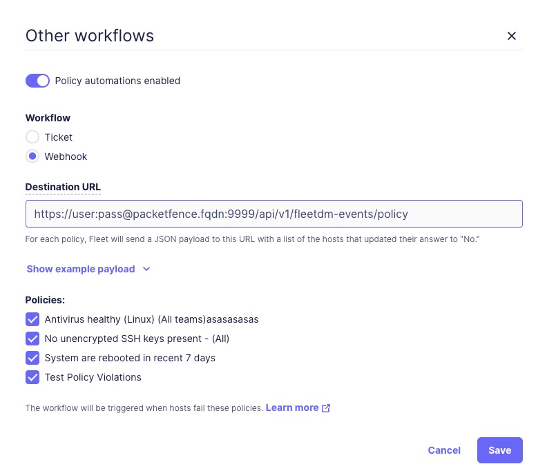
CVEs
- Login to FleetDM admin Panel → Software → Manage Automations.
- In the popup window, enable Vulnerability automations enabled, workflow: Webhook.
-
For destination URL, fill in
https://USER:PASS@packetfence.fqdn:9999/api/v1/fleetdm-events/cve. -
Replace
USERandPASSwith the credentials created for the FleetDM Events Handler user in PacketFence. Replacepacketfence.fqdnwith the domain name or IP address of the PacketFence server.
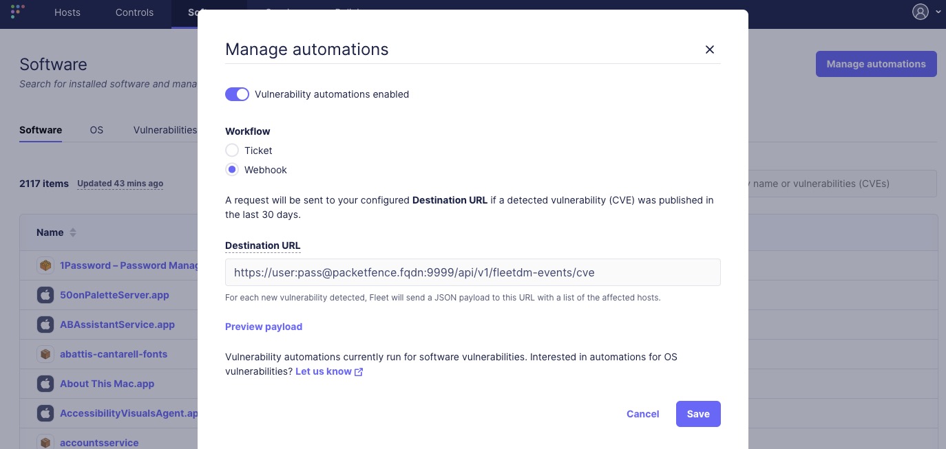
27.6.6. Test and Validate Webhooks
Test webhook functionality from PacketFence with these steps:
- Complete PacketFence and FleetDM configurations.
-
Login to the PacketFence node and use
journalctl -fto watch PacketFence logs. Or you can choose not to use "-f" and search occurrences of webhook calls instead as well. -
Use any tool such as
grepor built-in search highlights of your terminal application and search / watch for keywordfleetdm - Manually trigger a policy violation or CVE to verify the webhook API returns a 2xx response.
-
A successful report will be something like
api-frontend-access xx.xx.xx.xx - - [30/May/2024:12:42:00 -0400] "POST /api/v1/fleetdm-events/policy HTTP/2.0" 2xx xx "-" "Go-http-client/2.0"
27.6.7. Customize and Integrate with Security Events
FleetDM integrates with PacketFence’s Security Events system, enabling administrators to take actions such as isolating devices, sending notification emails, or triggering scripts when FleetDM reports policy violations or CVE vulnerabilities.
PacketFence 14.0+ includes 3 built-in security event templates: policy IDs "3500001", "3500002", and "3500003". Each template corresponds to a specific rule type supported in PacketFence. Modify these existing security events, add custom policy triggers, or use them as templates for new events. These security events are disabled by default and must be manually enabled.
27.6.8. How Security Events Work with FleetDM
PacketFence identifies and manages devices through its node list (Admin UI → Nodes). FleetDM uses unique host IDs to identify enrolled devices. PacketFence builds a mapping between these two identification systems.
The mapping process:
-
When FleetDM reports a policy violation or CVE vulnerability via webhook, the payload includes a host id.
-
PacketFence receives the payload, extracts the host id, and looks it up in the internal cache. If found, PacketFence uses the cached MAC address.
-
If the host ID is not cached, PacketFence makes a FleetDM API call to obtain the host’s primary MAC address and caches it. FleetDM API responses do not always guarantee a MAC address.
-
PacketFence compares the trigger rules of filtered security events. If a match is found, the security event triggers for each reported device.
primary_mac,
PacketFence will fail to trigger security event. You will see an error in
PacketFence logs like:
"unable to extract primary mac from host API response for host id", or
"unable to perform API call", etc.
Please check the logs if you believe a security event should be triggered.Security Event 3500001
Default security event for FleetDM policy violation checks. Uses regular
expressions to match policy names. For example, with a FleetDM policy named
"test policy" and a security event with FleetDM policy regex set to ^test,
the security event triggers when a device violates "test policy" in FleetDM.
Security Event 3500002
Default security event for FleetDM CVE Vulnerability checks. Uses regular expressions to match CVE names. For example, with a CVE named "CVE-2024-6387" and a security event trigger "FleetDM Vulnerability CVE Regex" set to "CVE\-2024", the security event triggers when a device is reported at risk for CVE-2024-6387.
Security Event 3500003
Default security event for high-risk FleetDM CVE Vulnerability checks. Compares the CVE severity value against a configured threshold. If the severity exceeds the threshold, the security event triggers. The "CVE Severity" value is a premium feature requiring a FleetDM subscription (see FleetDM’s official website for details) to be included in CVE Vulnerability webhooks.
Customized Email Templates
Email templates are located in
/usr/local/pf/html/captive-portal/templates/emails:
email-fleetdm-policy-violation.html for FleetDM policy violations.
email-fleetdm-cve.html for FleetDM CVE vulnerabilities.
Customized Additional Email Messages
Add extra information to emails sent to device owners or additional recipients without modifying email templates. Configure the additional message section when "email device owner" or "email recipient" is enabled using supported variables.
To use variables in the extra message template, quote them with [% ` and ` %].
For example, use [% mac %] to include the MAC address in the extra message.
Check the FleetDM payload example for all supported variables. The example payload appears when configuring webhooks for policies or CVEs in the FleetDM admin UI.
/usr/local/pf/conf/security_events.conf*). When
editing the file directly without PacketFence’s admin UI, quote variables as
[% ENV.BRL %] variable [% ENV.BRR %], where [% ENV.BRL %] is the double
quoted form of [% ` and `[% ENV.BRR %] is the double quoted form of ` %].
After changing the config file, reload with
`/usr/local/pf/bin/pfcmd configreload or
/usr/local/pf/bin/pfcmd configreload hard.28. Advanced Topics
Advanced PacketFence topics. PacketFence can be configured manually using configuration files instead of the admin interface (admin interface recommended).
/usr/local/pf/conf/pf.conf contains PacketFence general
configuration, including VLAN isolation mode settings.
Default parameters and descriptions are in
/usr/local/pf/conf/pf.conf.defaults.
Override default parameters by defining them in
/usr/local/pf/conf/pf.conf.
/usr/local/pf/conf/documentation.conf holds the complete list of all
available parameters.
All parameters accessible via admin interface Configuration tab. Web interface highly recommended for configuration changes.
28.1. Reports
Define reports in report.conf creating SQL queries to view
PacketFence database tables. Reports appear under Reports menu in admin
interface.
PacketFence includes preloaded reports optimized for common production
use-cases in reports.conf.defaults. Don’t modify this file; use for
working examples.
type=sql
(script/batch mode) increases query and transaction control.28.1.1. Configuration Attributes
Configure reports by editing /usr/local/pf/conf/report.conf and
adding a report section. Run /usr/local/pf/bin/pfcmd configreload
hard.
The admin interface builds the structured menu by splitting and separating all the section identifier’s by double colons "::". Identifiers without this separator are shown at the top level. Up to a maximum of 2 sets of double colons can be used for a maximum menu depth of 3 levels. All identifiers must be unique and any identifier partially reused by another sibling will make it inaccessible. (ex: [A::B] will lose its place as a report and become a parent category for [A::B::*] if it is also defined. Either rename the former to include a 3rd part, or rename the latter to use a different 1st or 2nd part.
[Top Category::Sub Category::Report]
The following attributes are available to define a report (* mandatory attributes are marked with an asterisk):
-
type*: The type of report. Usetype=abstractto use SQL Abstract andtype=sqlto use MySQL script/batch mode. Each of these types have their own additional attributes which are explained in more detail below. -
description*: A user-friendly description that provides more details about the report. Used as a title for all charts. -
charts: A comma delimited list of charts to display. Each chart is displayed in its own tab above the table data. There is no limit to the number of charts that can be defined. Charts are explained in more detail below. -
columns*: A comma separated list of columns or aliases that are displayed in the table from the SQL query (ex:node.mac,Node MAC). The table columns are displayed in the respective order. Columns can be aliased to a more friendly name, but these aliases must be used throughout the other attributes. -
date_limit: A PacketFence interval that defines the maximum date range allowed betweenstart_dateandend_date. The reports user is restricted from choosing a date range that exceeds this limit. This is used to prevent the MySQL query from consuming too much resources with large datasets. The duration is defined asdate_limit=[unit][interval](ex: date_limit=1D), where the unit is a positive integer and the interval is one of the following characters:-
s: second(s) -
m: minute(s) -
h: hour(s) -
D: Day(s) -
W: Week(s) -
M: Month(s) -
Y: Year(s)
-
-
formatting: A comma separated list of column or alias formatters. Each column is defined folowed by a colon and the internal PacketFence function used to format the column value for every row (ex:formatting=vendor:oui_to_vendor). This is used to format the query result columns using a function to access internal PacketFence memory. The supported formatters:-
oui_to_vendor: format a MAC OUI to a vendor.
-
-
has_date_range: [enabled|disabled] Display a datetime range and providestart_dateandend_datebindings. Seedate_limitto restrict the maximum date range. -
has_limit: [enabled|disabled] Display a limit selection and provide alimitbinding. -
node_fields: A comma delimited list of fields (columns or aliases) that will be clickable from the table of the Report and linked to the specific Node - only clickable if the reports' user has the "Node - View" admin role. All fields must be a valid PacketFence node identifier (mac). -
person_fields: A comma delimited list of fields (columns or aliases) that will be clickable from the table of the Report and linked to the specific User - only clickable if the reports' user has the "User - View" admin role. All fields must be a valid PacketFence user identifier (pid)`. -
role_fields: A comma delimited list of fields (columns or aliases) that will be clickable from the table of the Report and linked to the specific Role. All fields must be a valid PacketFence role identifier (category_id).
columnName reference with
simple queries that use a single table (ex: attribute=columnA,columnB). The
attributes must use tableName.columnName reference when using joins with 2+
tables (ex: attribute=tableA.columnA,tableB.columnB). Aliased columns can be
used with the table reference (ex: attribute=tableA.Alias A,tableB.Alias B).28.1.2. SQL Abstract
When type=abstract PacketFence uses Perl
SQL::Abstract::More to
automatically build the SQL query.
The following attributes are available when using type=abstract(* mandatory
attributes are marked with an asterisk):
-
base_conditions: A comma delimited list of conditions that is applied to the SQL query. Conditions should match the following format :field:operator:value(ex:auth_log.source:=:sms,auth_log.status:!=:completed). -
base_conditions_operator: [all|any] The logical SQL operator (AND|OR respectively) used with thebase_conditons. -
base_table*: The base SQL table used in the SQL query. -
date_field*: The table field (column) used to filter by the date range. When used the column will also be used for the default sorting, unlessorder_fieldsis explicitly defined. -
group_field: The field (column) to group the query results by. No grouping is performed if this field is empty or omitted. -
joins: The table(s), columns and aliases used to join on thebase_table. See example below and the following documentation. This attribute supports multi line blocks (heredoc), see below. -
order_fields: A comma delimited list of fields (columns) used to order the SQL query. The field should be prefixed of-if the sort should be made in descending order for the field (ex:-node.regdate,locationlog.start_time,+iplog.start_time). -
searches: A comma delimited list of searchable fields (columns) that are presented to the reports' user. This allows the user to optionally include additional criteria for the query. Each item is defined astype:Friendly Name:tableName.columnName(ex:searches=string:Owner:person.pid,string:Node:node.mac). Currently only the type string is supported.-
typedefines the type of the search, the only one currently supported isstring. -
Display Nameis the user-friendly name of the field for display. -
fieldis the SQL name of the field to search
-
IS and <> by = and !=, respectively.node.mac,
locationlog.role, …) so that they are not ambiguous. Wrap table names and
column names with backticks "``" to avoid naming issues with current and future
MySQL reserved words.Examples
View of the auth_log table:
[auth_log]description=Authentication report# The table to search frombase_table=auth_log# The columns to selectcolumns=auth_log.*# The date field that should be used for date rangesdate_field=attempted_at# The mac field is a node in the databasenode_fields=mac# Allow searching on the PID displayed as Usernamesearches=string:Username:auth_log.pid
In this simple example, select the whole content of the
auth_log table and use the date range on the attempted_at field as well as
search on the pid field when viewing the report.
View of the opened security events:
[open_security_events]description=Open security events# The table to search frombase_table=security_event# The columns to selectcolumns=security_event.security_event_id as "Security event ID",security_event.mac as "MAC Address", class.description as "Security eventdescription", node.computername as "Hostname", node.pid as "Username",node.notes as "Notes", locationlog.switch_ip as "Last switch IP",security_event.start_date as "Opened on"# Left join node, locationlog on the MAC address and class on the securityevent IDjoins=<<EOT=>{security_event.mac=node.mac} node|node=>{security_event.mac=locationlog.mac} locationlog|locationlog=>{security_event.security_event_id=class.security_event_id} class|classEOTdate_field=start_date# filter on open locationlog entries or null locationlog entries via theend_date fieldbase_conditions_operator=anybase_conditions=locationlog.end_time:=:0000-00-00,locationlog.end_time:IS:# The MAC Address field represents a nodenode_fields=MAC Address# The Username field represents a userperson_fields=Username
In the example above, the security_event table is left joined to the class, node and locationlog tables. Using that strategy we make sure all the security events are listed even on deleted nodes. Then, base conditions are added to filter out outdated locationlog entries as well as include devices without locationlog entries. Removing those conditions would lead to duplicate entries being shown since the report would reflect all the historical locationlog entries.
28.1.3. SQL
When type=sql PacketFence uses MySQL script/batch mode to manually build the
SQL query including the execution of multiple statements. This provides complete
query control as well as the ability to manage the SQL session and the SQL
transaction. This is the preferred mode where SQL optimization is needed to
execute complex queries, or for those more comfortable with raw (non-abstract)
SQL.
sql=SELECT * FROM sponsors;
Multiline block (heredoc) is required when executing multiple statements. Each statement should be terminated with a semi-color ";".
The following attributes are available when using type=sql:
-
bindings: A comma delimited list of ordered bindings to send to the SQL script (ex:bindings=tenant_id,start_date,end_date,cursor,limit). See Bindings below. -
cursor_type: [node|field_multi_field] Adds a cursor binding to the sql script that implements pagination of the results. The cursor is automatically handled in the admin interface, but its use in thesqlrequires special attention. If omitted the defaultnoneis used. More information about cursors is provided below. There are 2 types of cursors:-
cursor_type=field: Use a single field (column or alias) for the cursor. -
cursor_type=multi_field: Use multiple fields (columns or aliases) for the cursor. -
cursor_type=offset: Use integer based offset for the cursor. -
cursor_type=none: No cursor is used.
-
-
cursor_default: The default cursor used to conditionally query the results for the first page. On subsequent pages this is replaced with the results from N+1 row of the previous page, meaning the cursor for page 2 (withdefault_limit=25) will contain the value from the column of the 26th row from the previous page. -
cursor_field: A comma delimited list of fields (columns) used for pagination. -
default_limit: The default limit passed into the bindings of the SQL script. Whenhas_limit=enabledthe reports' user can override the default with a manual selection. -
sql: Either a single MySQL query, or a multi line block of statements within a heredoc (see Heredoc below).
28.1.4. Bindings
The bindings attribute defines an ordered comma delimited list of columns (or
aliases) that are made available to the sql script. There is no limit with the
number of bindings that can used and a binding can be repeated more than once.
The available bindings are:
-
tenant_id: The scoped tenant identifier of the reports' session. -
start_date,end_date: The start and end datetime. Formatted as "YYYY-MM-DD HH:mm:ss". Use native MySQL date functions to reformat it. -
cursor: On the first page this value is thecursor_default. On subsequent pages this value is taken from thecursor_fieldcolumn of the last result row from the previous page. When usingcursor_type=multi_fieldthe cursor is split into the bindings ascursor.0,cursor.1, etc. -
limit: Usesdefault_limit(+1, see pagination) unless overridden by the user.
Bindings are consumed in the sql using "?" in the same order that they are
defined.
[single binding]type=sqlbindings=limitsql=SELECT * FROM table LIMIT ?;default_limit=100has_limit=enabled
If a binding is needed more than once within the sql, it can either be defined
multiple times, or defined once and consumed to SET a MySQL variable.
[many bindings]type=sqlbindings=start_date,end_date,tenant_id,start_date,end_date,limitsql= << EOTSELECT*FROM tableAJOIN tableB ON tableA.id = tableB.idAND date BETWEEN ? AND ?WHERE tenant_id = ?AND date BETWEEN ? AND ?LIMIT ?;EOTdefault_limit=100has_date_range=enabledhas_limit=enabled
28.1.5. Pagination
Pagination is supported through the use of the cursor_type, cursor_default,
cursor_field, bindings and sql attributes. Pagination supports the use of
one to many columns. Special attention must be given to the order of the final
result set in order to utilize the cursor properly. Symptoms of too few pages,
or infinite loops through subsequent pages are signs of a mismatched cursor
and/or query results order.
The limit binding always has +1 added to it as PacketFence always consumes an
extra row to determine the cursor for the following page. Due to this all
conditional statements must be inclusive (ex: Bad operators "<, >", Good
operators: "⇐, >="). If the column value is not unique then
cursor_type=multi_field should be used instead to avoid infinite loops.
Examples of a single column cursor:
[all nodes in ascending order]type=sqlsql= <<EOTSELECT mac FROM node WHERE mac >= ? ORDER BY mac LIMIT ?;EOTbindings=cursor,limitcursor_type=fieldcursor_field=macdefault_cursor=00:00:00:00:00:00
[all nodes in descending order]type=sqlsql= <<EOTSELECT mac FROM node WHERE mac <= ? ORDER BY mac DESC LIMIT ?;EOTcolumns=macbindings=cursor,limitcursor_type=fieldcursor_field=macdefault_cursor=ff:ff:ff:ff:ff:ff
Example of a multi column cursor:
[all ip4log logs]type=sqlsql= <<EOTSELECTip4log.ip,ip4log.start_time,node.macFROM ip4logINNER JOIN nodeON ip4log.mac = node.macWHERE ip4log.start_time >= ?AND node.mac >= ?ORDER BY ip4log.start_time, node.macLIMIT ?;EOTcolumns=macbindings=cursor.0,cursor.1,limitcursor_type=multi_fieldcursor_field=start_time,macdefault_cursor=0000-00-00 00:00:00:00,00:00:00:00:00:00
28.1.6. Charts
Charts are defined as a comma delimited list using the chart attribute. An
optional "@" symbol can be used to delimit a chart name. A mandatory pipe
(vertical-bar) | is used to delimit the chart type and the fields. Within the
fields a colon ":" is used to delimit each of the fields (if more than one field
is necessary). The general syntax is:
charts=[pie,bar,parallel,scatter] [@ Chart Name] | field1 [:fieldN:...]
There are 4 types of charts available:
-
pie: A pie chart with 2 dimensions. Must contain 2 fields (charts=pie|field1:field2):-
field0: The dimensions label. -
field1: The dimensions value.
-
-
bar: A bar chart with 2 dimensions. Must contain 2 fields (charts=bar|field1:field2):-
field0: The dimensions label. -
field1: The dimensions value.
-
-
parallel: A parallel category (sankey) diagram with 2+ dimensions. Must contain 3+ fields (charts=parallel|field1:field2:field3[…:fieldN]):-
fieldN: The N dimensions label of 2+ fields. A category is created for each field and order is maintained. The palette is applied to the last field (right-most). -
fieldLast: The last field always contains the dimensions value.
-
-
scatter: A date/time based line graph with 1+ dimensions. The date/time column is always defined in the first field and the query should return this using the "YYYY-MM-DD HH:mm:ss" format.-
When only one field is defined (
charts=scatter|field1) then a value of 1 is implied for each row. -
When 2 fields are defined (
charts=scatter|field1:field2) then the 2nd field is used as the dimensions value. The query results are automatically aggregated to produce dimensions for several terms (year/month/week/day/hour/minute). -
When 3+ fields are defined
(
charts=scatter|field1:field2:field3[…:fieldN]) the automatic aggregation is disabled and a dimension is used for each field.
-
When only one field is defined (
28.1.7. Heredoc
The joins and sql attribute support multi line block statements. All
whitespace characters are preserved. All multi line statements are pure SQL,
thus the -- prefix can be used as a remark.
attribute= <<EOT-- multi-line-- block-- statementEOT
28.1.8. Troubleshooting
-
If the API request returns an error or an empty response refer to the
packetfence.logto obtain the full MySQL error message. - SQL scripts are transactional. After the script is run any variables or stored procedures created or temporary tables created are destroyed. Any locks obtained are released.
-
Modification to the configuration file only requires a
/usr/local/pf/bin/pfcmd configreload hardfor the changes to take effect. The admin interface will begin using the new script on its next request.
28.2. Admin Access
Manage access levels for PacketFence administrators. Go through Configuration → System Configuration → Admin Access. Then go to the source which authenticates administrator and create an administration rule and assign the desired Admin role. This functionality allows granular control on which section of the admin interface is available to whom.
28.2.1. Built-in roles
- ALL: Provides the user with all the admin roles without any exception.
- ALL_PF_ONLY: Provides the user with all the admin roles related to the PacketFence deployment (excludes switch login rights).
- Node Manager: Provides the user the ability to manage the nodes.
- User Manager: Provides the user the ability to manage other users.
- Security Event Manager: Provides the user the ability to manage the security events (trigger, open, close) for the nodes.
28.3. Guest pre-registration
Pre-registration is disabled by default. Once enabled, PacketFence’s firewall
and Apache ACLs allow access to the /signup page on the portal even from a
remote location. All that should be required from the administrators is to open
the perimeter firewall to allow access to PacketFence’s management
interface IP on port 443 and ensure a domain name to reach said IP is
configured (and that the SSL cert matches it). Then promote the
pre-registration link from the extranet web site: https://<hostname>/signup.
To minimally configure guest pre-registration, ensure that the
following statement is set under [guests_self_registration] in
/usr/local/pf/conf/pf.conf:
[guests_self_registration]preregistration=enabled
This parameter should be configured from the Configuration → Policies and Access Control → Connection Profiles → Profile Name section.
28.4. Content-Security-Policy (CSP)
The Content-Security-Policy HTTP response header tells modern browsers what can be accessed from a generated web page. The default policy is pushed for the captive portal and enforces that everything the browser executes comes from within PacketFence, with the exception of the configured network detection host that is by default the Inverse IP address.
If the portal is modified with content that needs to be accessed from PacketFence generated web pages, deactivate CSP through Configuration → System Configuration → Main Configuration → Advanced → CSP headers for Captive Portal.
28.5. pfacct: track bandwidth usage
Starting from v10, pfacct daemon is used to track bandwidth usage of nodes
using RADIUS Accounting or NetFlow v5 traffic. It is enabled by default and
replaced packetfence-radiusd-acct service. pfacct will store data into
bandwidth_accounting table. Using a security event with a bandwidth limit
trigger, you can limit data usage of the nodes. The admin interface also uses
bandwidth_accounting table informations to display online/offline status of
nodes. Bandwidth usage reports are available in Reports menu under
Accounting section.
To get bandwidth reports, security events or online/offline
features, enable 'Process Bandwidth Accounting' in Configuration
→ System Configuration → RADIUS → General menu. pfacct service needs to be
restarted to apply changes.
28.5.1. NetFlow traffic
pfacct can get NetFlow traffic from two kind of sources:
- network devices which send directly NetFlow traffic to PacketFence
- inline L2/L3 networks (using NetFlow kernel module)
By default, pfacct listens NetFlow traffic on localhost, using udp/2056
port to not conflict with the fingerbank-collector (which listens NetFlow
traffic on all interfaces).
pfacct must be able to map an IP address to a MAC address (from NetFlow
traffic) in order to create a record in bandwidth_accounting table. It means
that PacketFence needs to be aware of IP addresses of the nodes (default
behavior on inline L2/L3 networks).
Adjust pfacct configuration based on the NetFlow traffic source.
NetFlow traffic from network devices
Configure the following:
-
make
pfacctlistens on IP address where you want to receive NetFlow traffic usingnetflow_addresssetting in Configuration → System Configuration → Services menu - enable NetFlow on all networks in Configuration → System Configuration → Advanced menu
Then restart packetfence-pfacct services for it to take effect.
NetFlow traffic from inline L2/L3 networks
Enable Netflow Accounting Enabled setting when defining an inline network.
If NetFlow on all networks is enabled in Configuration → System
configuration → Advanced menu, pfacct will collect NetFlow bandwidth usage
for all networks instead of the ones defined in
/usr/local/pf/conf/networks.conf.
Then restart packetfence-pfacct services for it to take effect.
28.6. Kafka configuration
28.6.1. Setting the configuration for a standalone
To setup a Kafka standalone you need the following information.
Node ID, Hostname and IP address. (run the hostname command on the server, packetfence is the example)
- hostname 172.16.3.1
The IP addresses of the clients (the server itself and the external IP addresses)
- 172.16.3.1 (The server ip)
- 172.16.4.1 (An external IP)
Username and passwords
- admin: admin-pass
- user: pass
A unique cluster id which could be generated by the command below.
uuidgen | tr -d '-' | base64 | cut -b 1-22
Example
[packetfence]KAFKA_NODE_ID=1KAFKA_ADVERTISED_LISTENERS=INTERNAL://172.16.3.1:9094,EXTERNAL://172.16.1.100:9092,PF://100.64.0.1:9095,PFCONNECTOR://127.0.0.1:9096[auth user]pass=pass[admin]pass=admin-passuser=admin[iptables]clients=172.16.3.1,172.16.4.1cluster_ips=172.16.3.1[cluster]KAFKA_LOG_DIRS=/usr/local/pf/var/kafkaCLUSTER_ID=Y2I2MTdkMGNlMjI4NDUyMmKAFKA_CONTROLLER_LISTENER_NAMES=CONTROLLERKAFKA_LISTENER_SECURITY_PROTOCOL_MAP=CONTROLLER:PLAINTEXT,INTERNAL:PLAINTEXT,EXTERNAL:SASL_PLAINTEXT,PF:PLAINTEXT,PFCONNECTOR:PLAINTEXTKAFKA_INTER_BROKER_LISTENER_NAME=INTERNALKAFKA_LISTENERS=PF://0.0.0.0:9095,INTERNAL://0.0.0.0:9094,CONTROLLER://0.0.0.0:9093,EXTERNAL://0.0.0.0:9092,PFCONNECTOR://0.0.0.0:9096KAFKA_OPTS=-Djava.security.auth.login.config=/usr/local/pf/conf/kafka/kafka_server_jaas.confKAFKA_CONTROLLER_QUORUM_VOTERS=1@172.16.3.1:9093KAFKA_SASL_ENABLED_MECHANISMS=PLAINKAFKA_PROCESS_ROLES=broker,controllerKAFKA_OFFSETS_TOPIC_REPLICATION_FACTOR=1
28.6.2. Setting the configuration of the Kafka cluster
To setup a Kafka cluster you need the following information.
Node ID, Hostname and IP address, of each member.
- 1 hostname1 172.16.3.1
- 2 hostname2 172.16.3.2
- 3 hostname3 172.16.3.3
The IP addresses of the clients
- 172.16.4.1
- 172.16.4.2
Username of passwords
- admin: admin-pass
- user1: pass1
- user2: pass2
A unique cluster id which could be generated by the command below.
uuidgen | tr -d '-' | base64 | cut -b 1-22
Example
## Iptables rules[iptables]# The list of clientclients=172.16.4.1,172.16.4.2# All the IP address of the cluster memberscluster_ips=172.16.3.1,172.16.3.2,172.16.3.3#[auth user1]pass=pass1[auth user2]pass=pass2#The Admin username and password[admin]user=adminpass=admin-pass#Global ENV variables[cluster]#The unique Cluster IDCLUSTER_ID=MkU3OEVBNTcwNTJENDM2QkKAFKA_CONTROLLER_LISTENER_NAMES=CONTROLLER# List out each member using the following format <id>@<ip>:9093 comma separatedKAFKA_CONTROLLER_QUORUM_VOTERS=1@172.16.3.1:9093,2@172.16.3.2:9093,3@172.16.3.3:9093KAFKA_INTER_BROKER_LISTENER_NAME=INTERNALKAFKA_LISTENER_SECURITY_PROTOCOL_MAP=CONTROLLER:PLAINTEXT,INTERNAL:PLAINTEXT,EXTERNAL:SASL_PLAINTEXT,PF:PLAINTEXTKAFKA_LISTENERS=PF://0.0.0.0:9095,INTERNAL://0.0.0.0:29092,CONTROLLER://0.0.0.0:9093,EXTERNAL://0.0.0.0:9092KAFKA_LOG_DIRS=/usr/local/pf/var/kafkaKAFKA_OFFSETS_TOPIC_REPLICATION_FACTOR=2KAFKA_OPTS=-Djava.security.auth.login.config=/usr/local/pf/conf/kafka/kafka_server_jaas.confKAFKA_PROCESS_ROLES=broker,controllerKAFKA_SASL_ENABLED_MECHANISMS=PLAIN...##Member specific ENV variables##List each cluster member using the following format#[<hostname>]#KAFKA_NODE_ID=<id>#KAFKA_ADVERTISED_LISTENERS=INTERNAL://<ip>:29092,EXTERNAL://<ip>:9092#[hostname1]KAFKA_NODE_ID=1KAFKA_ADVERTISED_LISTENERS=INTERNAL://172.16.3.1:29092,EXTERNAL://172.16.3.1:9092,PF://100.64.0.1:9095[hostname2]KAFKA_NODE_ID=2KAFKA_ADVERTISED_LISTENERS=INTERNAL://172.16.3.2:29092,EXTERNAL://172.16.3.2:9092,PF://100.64.0.1:9095[hostname3]KAFKA_NODE_ID=3KAFKA_ADVERTISED_LISTENERS=INTERNAL://172.16.3.3:29092,EXTERNAL://172.16.3.3:9092,PF://100.64.0.1:9095
28.6.3. FingerBank collector kafka configuration
FingerBank collector can be configured to store the NetFlow, sFlow, IPFIX traffic to Kafka in order to allow pfflow to process it.
Here a sample of configuration that can be use with the Kafka server configured above.
[collector]additional_env=<<EOTCOLLECTOR_DISABLE_KAFKA=falseCOLLECTOR_KAFKA_HOSTS=100.64.0.1:9095COLLECTOR_DISABLE_IPFIX_SERVICE=falseCOLLECTOR_DISABLE_SFLOW_KAFKA=falseCOLLECTOR_KAFKA_USER=COLLECTOR_KAFKA_PASS=EOT
28.6.4. pfflow configuration
pfflow cron task can be configured to talk to kafka in order to compile the netflow events to json payloads.
Here is the configuration that can be use in pfcron.conf to communicate with the Kafka server configured above.
[pfflow]## status## If the task is enabledstatus=enabled## kafka_brokers## Kafka Brokers to read fromkafka_brokers=100.64.0.1:9095## uuid## The UUID of the packetfence aggregatoruuid=f1e53295-c052-4602-a02f-8a6c90346c08## kafka_user## The Kafka usernamekafka_user=## kafka_pass## The Kafka passwordkafka_pass=##filter_events=1
28.6.5. Restarting Services
systemctl restart packetfence-kafkasystemctl restart packetfence-fingerbank-collectorsystemctl restart packetfence-pfcron
Monitoring with Netdata Cloud
PacketFence includes Netdata that is pre-installed and configured for most use-cases.
The metrics are displayed in 2 separate sections
- Dashboard: This section displays the metrics collected by pfstats for the unregistration/registration status of all nodes managed by PacketFence.
- Monitoring: This section displays system metrics collected by Netdata for the local host (standalone), or all hosts in a cluster.
All metrics are retained for a maximum of 28 days. Older metrics are automatically pruned to limit disk usage. To increase the retention rate edit the configuration and restart the service:
vi /usr/local/pf/conf/monitoring/netdata.conf[db]retention = 2419200 # 28 days (seconds)
Dashboard
The dashboard displays the metrics collected by pfstats for the unregistration/registration status of all nodes managed by PacketFence. These metrics are common across all cluster members, therefore a complete view is displayed from any host that is a member of the same cluster.
Monitoring: The monitoring section displays the metrics collected by netdata for the health of the system. Wether the setup is standalone, or a cluster, a section is dedicated to each host in the deployment. When using one host to view metrics from another, the external host must be up and running.
The User Interface (Web Admin) now includes:
- A duration selection that can be used to zoom-in/zoom-out the timeline, up to a maximum of 28 days. If the retention rate is increased, these selections will remain the same.
- A "Netdata Cloud" button that opens a new window with the Netdata UI. Once launched the user can login anonymously (bottom-right), or the session_id can be used to attach the PacketFence instance to the Netdata Cloud.
- A zoom-able popup that displays and compares a single metric for all members in the cluster. Click any metric title to open this popup.
To obtain the local Netdata random session identifier:
cat /usr/local/pf/var/netdata-lib/netdata_random_session_id
Once connected to Netdata Cloud, Netdata alerts will be sent to the email address used to register the Netdata Cloud account.
To attach all members of a cluster, each member has its own unique session id; where each must be used to login to Netdata Cloud manually.
Restarting Service
systemctl restart packetfence-netdata
Dynamic iptables and ip6tables rules
Iptables and ip6tables are dynamic and each service is adding or removing port(s) according to their needs.
/!\ Packetfence is NOT fully compatible with ipv6 /!\
Default ipv6 rules are set to protect Packetfence server and for convenient usage.
Starting Service
systemctl start packetfence-iptablessystemctl start packetfence-ip6tables
Restarting the service should be done only when there is a modification on /usr/local/pf/lib/pf/iptables.pm or on /usr/local/pf/lib/pf/ip6tables.pm.
Once started, the iptable service is checking modifications on the directory /usr/local/pf/var/conf/iptables/ and on the file /usr/local/pf/conf/iptables-custom.conf.inc.
Once started, the ip6table service is checking modifications on the directory /usr/local/pf/var/conf/ip6tables/ and on the file /usr/local/pf/conf/ip6tables-custom.conf.inc.
Any modification will result in a restart of iptables and ip6tables configuration rules.
Each service generated rules can be find in the directory /usr/local/pf/var/conf/iptables/ and /usr/local/pf/var/conf/ip6tables/.
Reload iptables rules
/usr/local/pf/bin/pfcmd is offering two ways to reload iptables configuration.
The soft reload will trigger rebuild iptables rules according to running services.
The hard reload will trigger a flush of all tables, a remove of all config files
from the directory /usr/local/pf/var/conf/iptables/ and then do the same a soft reload.
/usr/local/pf/bin/pfcmd reloadiptablesrules/usr/local/pf/bin/pfcmd reloadiptablesrules hard
Reload ip6tables rules
/usr/local/pf/bin/pfcmd is offering two ways to reload ip6tables
configuration.
The soft reload will trigger rebuild ip6tables rules according to running
services.
The hard reload will trigger a flush of all tables, a remove of all config files
from the directory /usr/local/pf/var/conf/ip6tables/ and then do the
same a soft reload.
/usr/local/pf/bin/pfcmd reloadip6tablesrules/usr/local/pf/bin/pfcmd reloadip6tablesrules hard
Setting custom iptables rules
It is possible to create custom iptables entry from a json file located in /usr/local/pf/conf/iptables-custom.conf.inc.
An example of the file is available here /usr/local/pf/conf/iptables-custom.conf.inc.example.
That file is a json file will add rules on top of all other Packetfence rules for each tables or chains. The entry should only contain the rule without the "-A", the table and the chain.
For example: to open tcp port 123, and udp port 234 with interface the eth0 on filter→INPUT, the file will be:
{"filter" : {"FORWARD" : [],"INPUT" : ["# allow tcp port 123 and udp port 234 on eth0 interface","-i eth0 --protocol tcp --match tcp --dport 123 --jump ACCEPT","-i eth0 -p udp -m udp --dport 234 --jump ACCEPT"],"OUTPUT" : []},"mangle" : {"PREROUTING" : [],"INPUT" : [],"FORWARD" : [],"OUTPUT" : [],"POSTROUTING" : []},"nat" : {"POSTROUTING" : [],"OUTPUT" : [],"PREROUTING" : []}}
Setting custom ip6tables rules
It is possible to create custom ip6tables entry from a json file located in
/usr/local/pf/conf/ip6tables-custom.conf.inc.
An example of the file is available here
/usr/local/pf/conf/ip6tables-custom.conf.inc.example.
That file is a json file will add rules on top of all other Packetfence rules
for each tables or chains. The entry should only contain the rule without the
"-A", the table and the chain.
For example: to open tcp port 123, and udp port 234 with interface the eth0 on
filter→INPUT, the file will be:
{"filter" : {"FORWARD" : [],"INPUT" : ["# allow tcp port 123 and udp port 234 on eth0 interface","-i eth0 --protocol tcp --match tcp --dport 123 --jump ACCEPT","-i eth0 -p udp -m udp --dport 234 --jump ACCEPT"],"OUTPUT" : [],"RFC3964_IPv4" => []},"raw" : {"PREROUTING" : [],"OUTPUT" : []}}
Check iptables or ip6tables applied rules
Generated and applied iptables rules are available in /usr/local/pf/var/conf/iptables_generated_rules.conf.
Generated and applied ip6tables rules are available in /usr/local/pf/var/conf/ip6tables_generated_rules.conf.
It is also possible to check rules with the following command lines:
# iptables ipv4iptables -L -n -v -t filteriptables -L -n -v -t mangleiptables -L -n -v -t nat# ip6tables ipv6ip6tables -L -n -v -t filterip6tables -L -n -v -t raw
29. Export/Import mechanism
This section covers export/import mechanism available since PacketFence 11.0. It can be used to automate parts of upgrades or to restore PacketFence installations.
29.1. Assumptions and limitations
- Export is supported on any PacketFence version above 10.3
- With export from 10.3, import is supported on any PacketFence version after 11.0 except if using mariadb-backup for mysql backup.
-
If using mariabd-backup and wanting to jump to Debian 12 (packetfence 14.0 or later), it will be necessary to:
- be at least on Packetfence version 11.0
- follow these steps in order to backup the database with the right mariadb-backup version.
-
The import process needs to be done on a standalone server. Restoring directly to clusters is currently unsupported
-
NOTE: Once restored to the standalone server, it can be made a
cluster by joining other machines to it and creating the
cluster.confbut this is relatively advanced and out of scope of this document
-
NOTE: Once restored to the standalone server, it can be made a
cluster by joining other machines to it and creating the
- Restoring on a fresh install of PacketFence is recommended although restoring on an existing instance can work but results may vary
- The import process will not modify network cards configuration of the server: it will only update PacketFence IP configuration. Recommend defining targeted IP addresses on network cards before running import process even if it can be done at end of import process.
- The import process will not join server to Active Directory domains automatically. Rejoin server manually.
-
The import process will only restore the files that can be edited via the admin interface which include:
-
Standard configuration files in
/usr/local/pf/conf/*.conf -
Connection profiles HTML templates in
/usr/local/pf/html/captive-portal/profile-templates/ -
Standard certificates
-
/usr/local/pf/conf/ssl/* -
/usr/local/pf/raddb/certs/*
-
-
Standard configuration files in
-
Here is a short list of the configuration files that will not be restored. Changes to these files need to be migrated manually. This list is not meant to be complete:
-
/usr/local/pf/conf/radiusd/* -
/usr/local/pf/conf/log.conf -
/usr/local/pf/conf/log.conf.d/* -
/usr/local/pf/conf/iptables.conf.tt(but/usr/local/pf/conf/iptables-custom.conf.incand/usr/local/pf/conf/ip6tables-custom.conf.incare restored) -
/usr/local/pf/conf/cluster.conf
-
29.2. Export on current installation
show status like 'wsrep_incoming_addresses'; inside the MariaDB
instance and the first IP will be the one where to perform the export
process.29.2.1. Installation (for PacketFence version 10.3 only)
On PacketFence version 10.3, install packetfence-export package
using following instructions:
yum localinstall https://www.packetfence.org/downloads/PacketFence/RHEL8/packetfence-export-15.1.el8.noarch.rpm
wget https://www.packetfence.org/downloads/PacketFence/debian/packetfence-export_15.1.debdpkg -i packetfence-export_15.1.deb
29.2.2. Start the export process
The export process will try to use files created by the nightly backup done at 00:30am everyday. If this is fine and the latest data is not needed, then skip this step. Otherwise to have the latest data and configuration in the export, run:
/usr/local/pf/addons/exportable-backup.sh -f /tmp/export.tgz
The command above will create the export archive in /tmp/export.tgz. It will
now be necessary to copy this file to the new server using SCP or the preferred
mechanism.
29.3. Import on new installation
First have a PacketFence installation with latest version done on a standalone server following the instructions in our install guide. It is not necessary to go through the configurator unless wanting to modify IP settings of the server.
29.3.1. Note on Mariabackup
The import script could try to install Mariabackup to import the database dump. If that is the case, it will remove it at end of import.
Consequently, if Mariabackup was installed before running the import script, ensure that Mariabackup is still installed at end of import.
29.3.2. Start the import process
The import script will guide through the restore of the database, if necessary it will assist with the configuration files and adjust the PacketFence IP configuration.
To start the import process using the export archive made on the current installation:
/usr/local/pf/addons/full-import/import.sh -f /tmp/export.tgz
Once the process is completed, the following should appear:
Completed import of the database and the configuration! Complete any necessaryadjustments and restart PacketFence
If that’s not the case, check the output above to understand why the process failed.
If any issues are experienced during import, run it again.
If all goes well, restart services using following instructions.
Additional steps to build or rebuild a cluster
To build or rebuild a cluster, follow instructions in Cluster setup section.
If the previous installation was a cluster, some steps may not be necessary
to do. The export archive will contain the previous
cluster.conf file.
30. PacketFence Certificates (for v11.2 and later)
30.1. Introduction
30.1.1. Context and Objectives of the Documentation
This documentation for PacketFence v11.2+ provides implementation and renewal instructions for SSL/TLS certificates for HTTP (captive web portal + web admin) and RADIUS.
Captive portal provides user authentication on wireless/wired networks by redirecting users to authentication pages for login information. RADIUS protocol handles user authentication and authorization on networks.
30.1.2. Definitions and Basic Concepts
Understanding basic security and certificate concepts is essential for SSL/TLS certificate implementation and management:
- SSL/TLS: Secure Sockets Layer/Transport Layer Security, a security protocol that allows encrypting communications between a client and a server.
- SSL/TLS certificate: an electronic file that contains information to verify the identity of a server and establish a secure connection.
- Certificate Authority (CA): an entity that issues and manages SSL/TLS certificates by verifying the identity of the certificate owner.
- Intermediate Certificate: a type of digital certificate that is issued by a trusted root certificate authority and is used to establish a chain of trust between the root certificate and end-entity certificates.
- Private key: an encryption key used to protect confidential information, known only to the certificate owner.
- Public key: an encryption key used to decrypt information encrypted using the private key, known to all users.
These concepts aid SSL/TLS certificate understanding and implementation for captive web portal and RADIUS.
30.1.3. Important notes before starting
This documentation covers PacketFence v11.2+.
Wildcard certificates restricted to HTTP only; cannot be used for RADIUS. Recommend using single certificate for both HTTP and RADIUS to simplify management.
30.2. Why a certificate
30.2.1. Generate a Certificate Signing Request (CSR)
To implement an SSL/TLS certificate for HTTP (captive web portal + web admin) and/or RADIUS, the first step is to generate a Certificate Signing Request (CSR). The CSR includes information about the organization requesting the certificate, the domain name of the captive portal, and the private key that will be used to encrypt communications.
Generating a CSR from HTTP or RADIUS is strictly the same. One CSR is needed to add a certificate for both HTTP and RADIUS. In this case, the same private key can be used for HTTP and RADIUS.
Example: If the CSR is generated through HTTP, copy the HTTPs server private key to the RADIUS server private key. The private key can be found on the web admin Configuration → System Configuration → SSL Certificates → Edit HTTP Certificates
- Log on the admin web interface (GUI)
- Go to Configuration → System Configuration → SSL Certificates
- Click on “Generate Signing Request (CSR)
- Complete the following using personal information
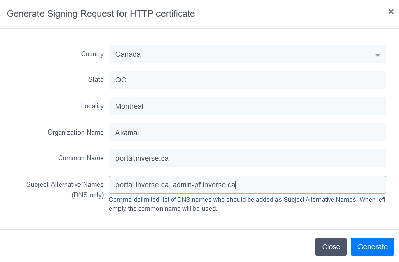
This capture have been made on PacketFence v13. If Packetfence Version is a lower version (not under v11.2), Subject Alternative Names will be automatically generated from Common Name field.
- Save CSR to secure location; required for certificate renewal.
30.2.2. Submit the CSR to a Certificate Authority (CA)
Once the CSR is generated, the next step is to submit it to a Certificate Authority (CA) for validation and issuance of the SSL/TLS certificate. There are many CAs to choose from, and it is important to select a reputable one that is trusted by major web browsers.
To submit the CSR to a CA, follow these steps:
- Select a CA and follow their instructions for submitting a CSR.
- The Subject Alternative Name must exactly match the captive portal FQDN in Configuration → System Configuration → General Configuration.
- Ensure that the selected Certificate Authority (CA) supports X509 in base 64 format.
- Provide the CSR and any other required information, such as payment and proof of identity.
- Wait for the CA to validate the CSR and issue the SSL/TLS certificate.
- Download the certificate in Apache format (base 64).
In the event that several types of certificates are offered, like in the following example:
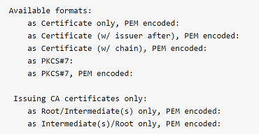
Choose as Certificate (w/ issuer after), PEM encoded:
It can be different from one issuer to another.
30.2.3. Install the SSL/TLS HTTP Certificate on the Server
Once the SSL/TLS certificate is received from the Certificate Authority (CA), the final step is to install it on PacketFence. This involves configuring the web server to use the SSL/TLS certificate for encrypted communications.
To install the SSL/TLS certificate, follow these steps:
- Open the web admin interface.
- Go to Configuration → System Configuration → SSL Certificates → HTTP → Edit HTTP Certificates .
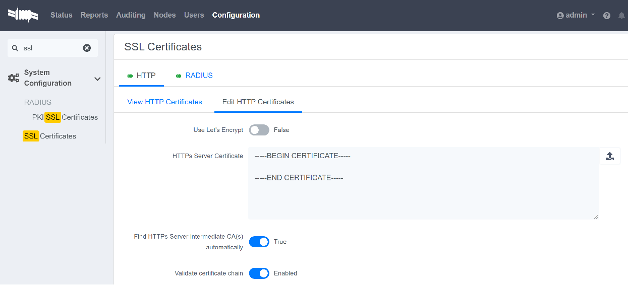
- Import or open the certificate file (.crt) with a text editor and copy/paste the content into the "HTTPs Server Certificate" field.
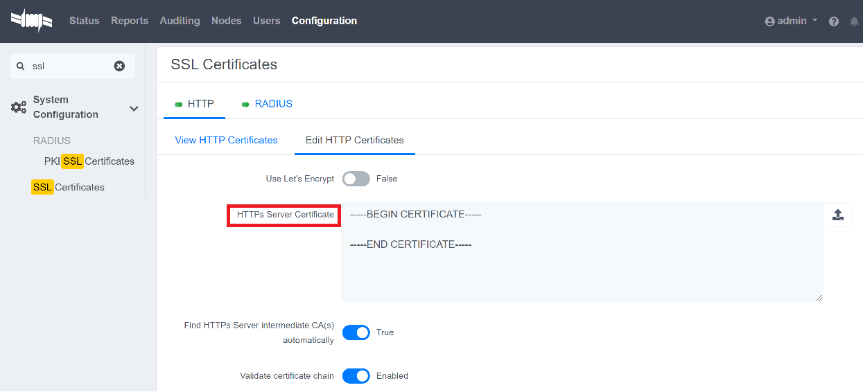
- Turn on the options "Find HTTPs intermediate CA(s) automatically" and "Validate certificate chain".
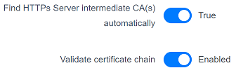
-
Restart
haproxy-adminandhaproxy-portal, one server at a time. This can be done through the web admin page: Status → Services .
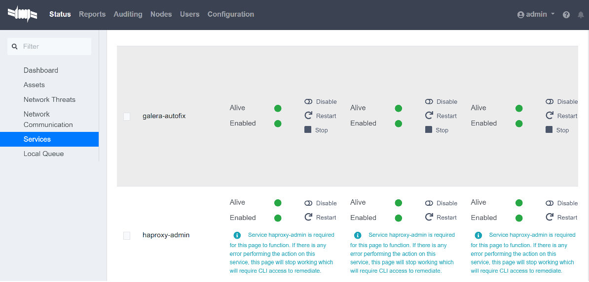
Alternatively, one server at a time, the following CLI commands can be run on each servers:
systemctl restart packetfence-haproxy-adminsystemctl restart packetfence-haproxy-portal
By following these steps, a SSL/TLS certificate for HTTP (captive web portal + web admin) has been implemented and provide a secure connection for user authentication.
30.2.4. Install the SSL/TLS RADIUS Certificate on the Server
Once the SSL/TLS certificate is received from the Certificate Authority (CA), the final step is to install it on the RADIUS server. This involves configuring the RADIUS server to use the SSL/TLS certificate for encrypted communications.
Wildcard certificate is strictly restricted to HTTP, it can’t be used for RADIUS.
To install the SSL/TLS certificate on the RADIUS server, follow these steps:
- Open the web admin interface.
- Go to Configuration → System Configuration → SSL Certificates → RADIUS → Edit RADIUS Certificates.
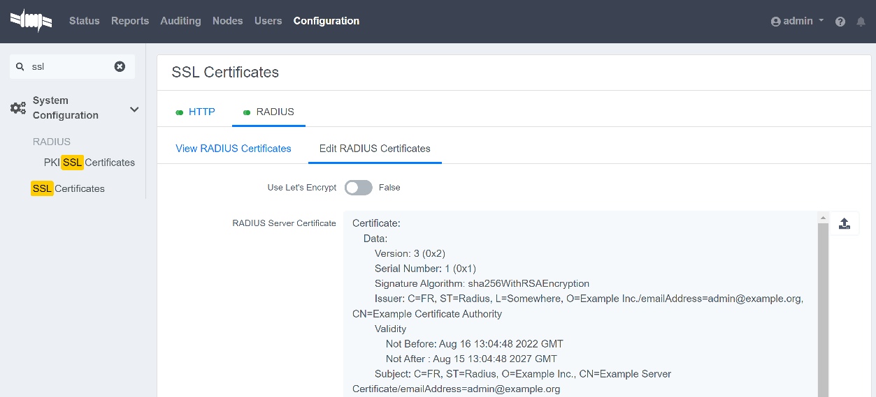
- Import or open the certificate file (.crt) with a text editor, then copy and paste the key into the "RADIUS Server Certificate" field.
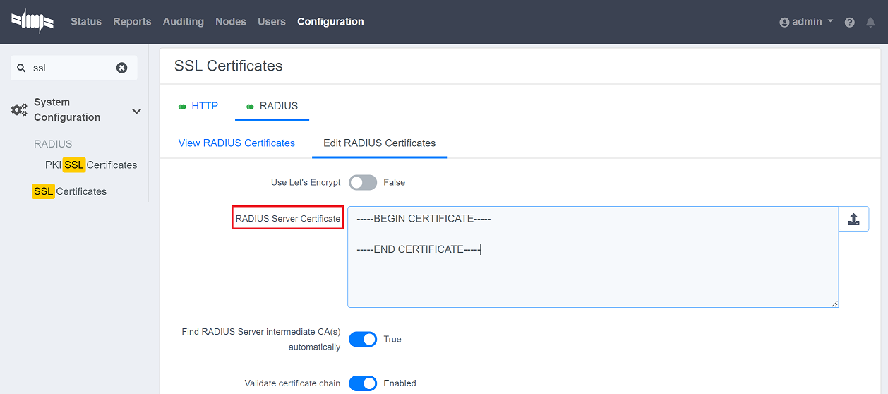
- Turn on the "Find RADIUS Server intermediate CA(s) automatically" and "Validate certificate chain" option.
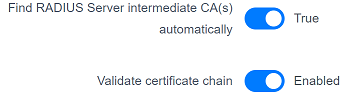
If a private certificate (that is not signed by a public Certification Authority CA) is used, disable "Find RADIUS Server intermediate CA(s) automatically" and add manually all needed "Intermediate CA certificate(s)"
-
Restart all
radiusdservices that are running, includingradius-auth,radiusd-load-balancer,radiusd-acct,radiusd-eduroam, andradiusd-cli. Restart them one server at a time. On the web admin page, go to Status → Services.
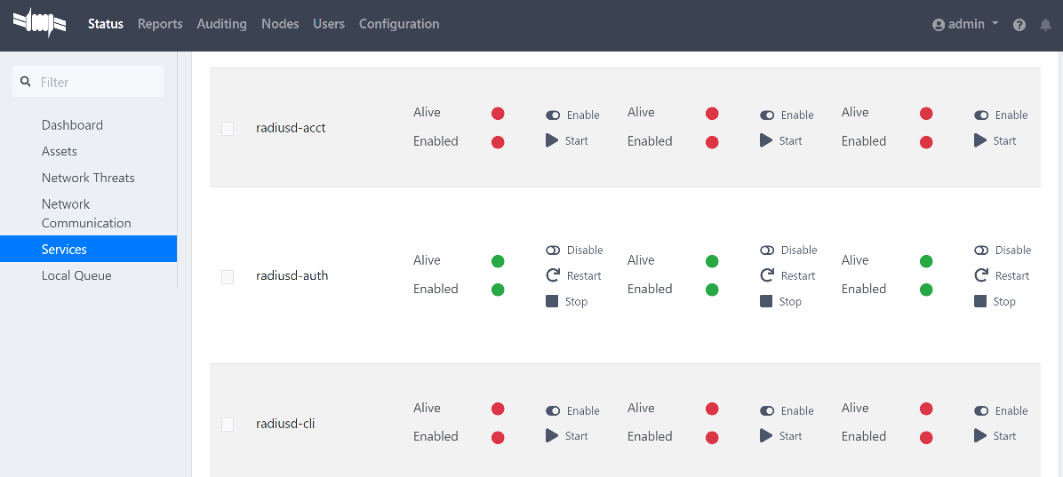
Alternatively, one server at a time, the following CLI commands can be run on each servers:
/usr/local/pf/bin/pfcmd service radiusd restart
30.3. From an existing certificate
If an existing certificate is already used, then there is already two dedicated files: - a certificate in base64 - a private key If the certificate and the private key are in one file, it is possible to extract them with command lines available here: Useful commands.
30.3.1. Install the SSL/TLS HTTP Certificate on the server
Follow the same step of Install the SSL/TLS HTTP Certificate on the Server but before saving the configuration and restarting the services add this step:
-
Import or open the private key file (.key) and copy/paste the content into the
RADIUS Server Private Keyfield.
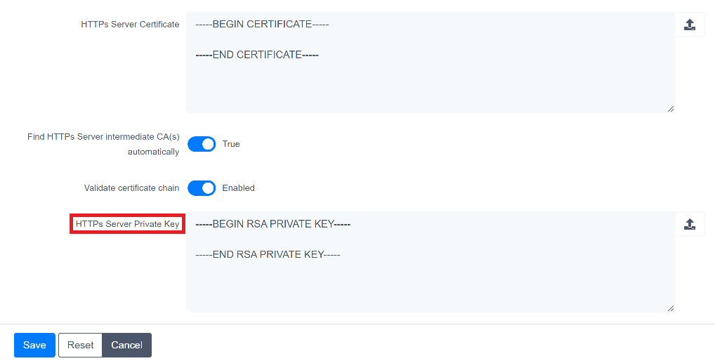
30.3.2. Install the SSL/TLS RADIUS certificate on the server
Follow the same step of Install the SSL/TLS RADIUS Certificate on the Server but before saving the configuration and restarting the services add this step:
-
Import or open your private key file (.key) and copy/paste the content into the
RADIUS Server Private Keyfield.
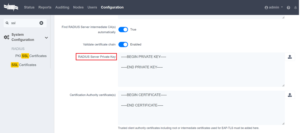
30.4. Renewal certificate with a CSR
When it is time to renew a certificate, it is possible to reuse an existing CSR.
There are two use cases:
- The CSR has been generated from PacketFence web admin, then follow these instructions under Why a certificate section:
- The CSR has been generated from another tool, then follow these instructions under From an existing certificate section:
30.5. Renew a certificate without the CSR
If no CSR is available, please restart from here Why a certificate.
30.6. Renew a certificate signed by the PF_PKI
The following steps explains how to renew HTTP/Radius certificates in PacketFence when they are signed by PF-PKI.
-
Locate the Certificate:
- Go to Configuration → Integration → PKI → Certificates.
- Search using the Common Name (CN) of the certificate.
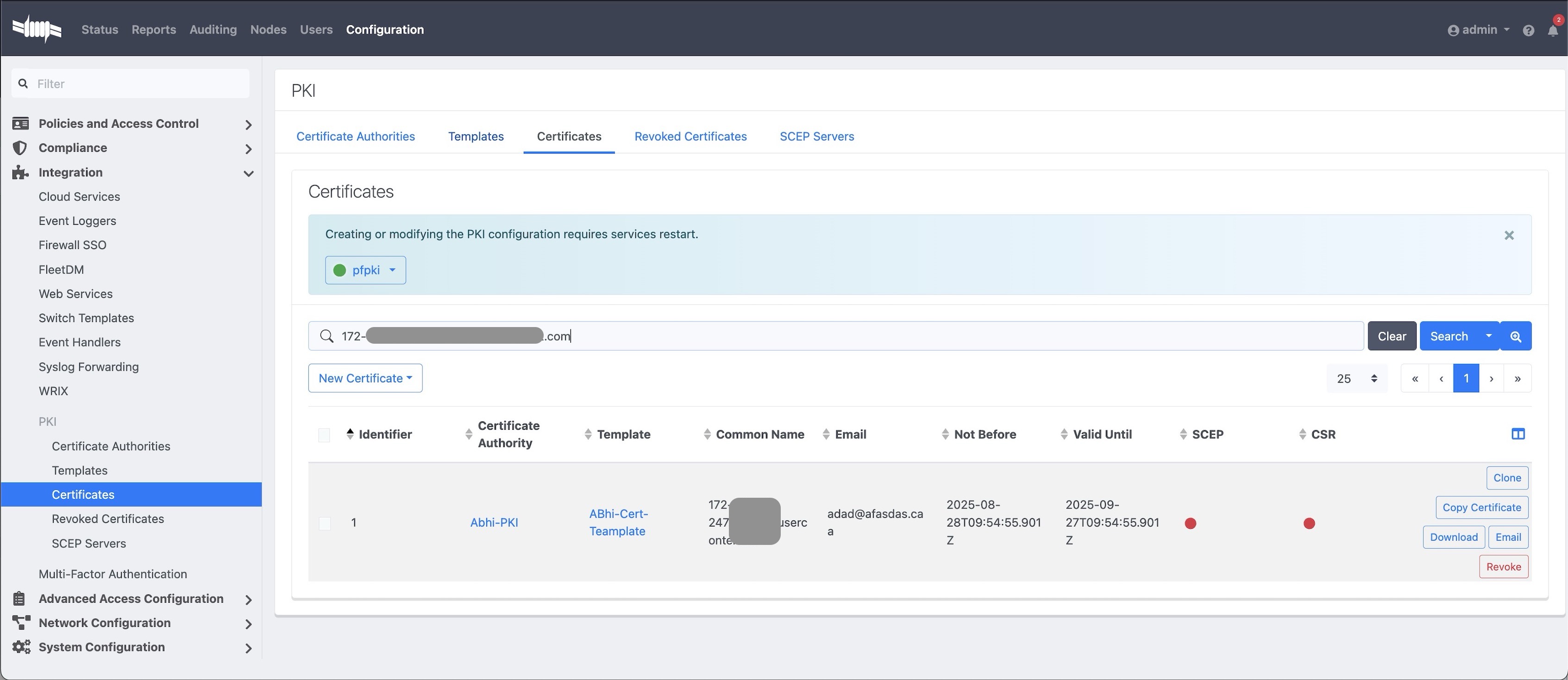
-
Open and Resign the Certificate:
- Open the certificate entry.
- Click Resign.
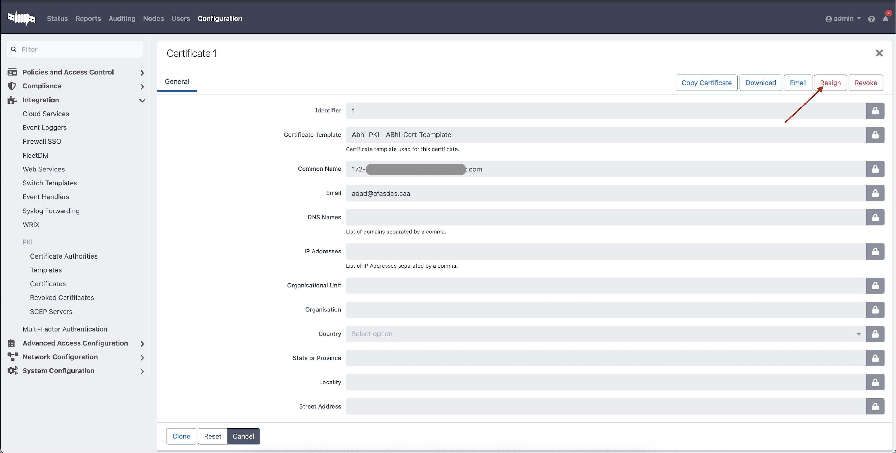
-
Fill the Resign Form:
- Keep the same details (CN, Email, etc.) as the existing certificate.
- Click Resign to generate a renewed certificate.
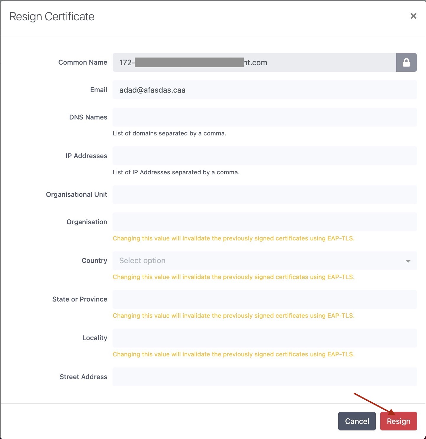
-
Copy the Renewed Certificate:
- After resigning, copy the updated certificate.
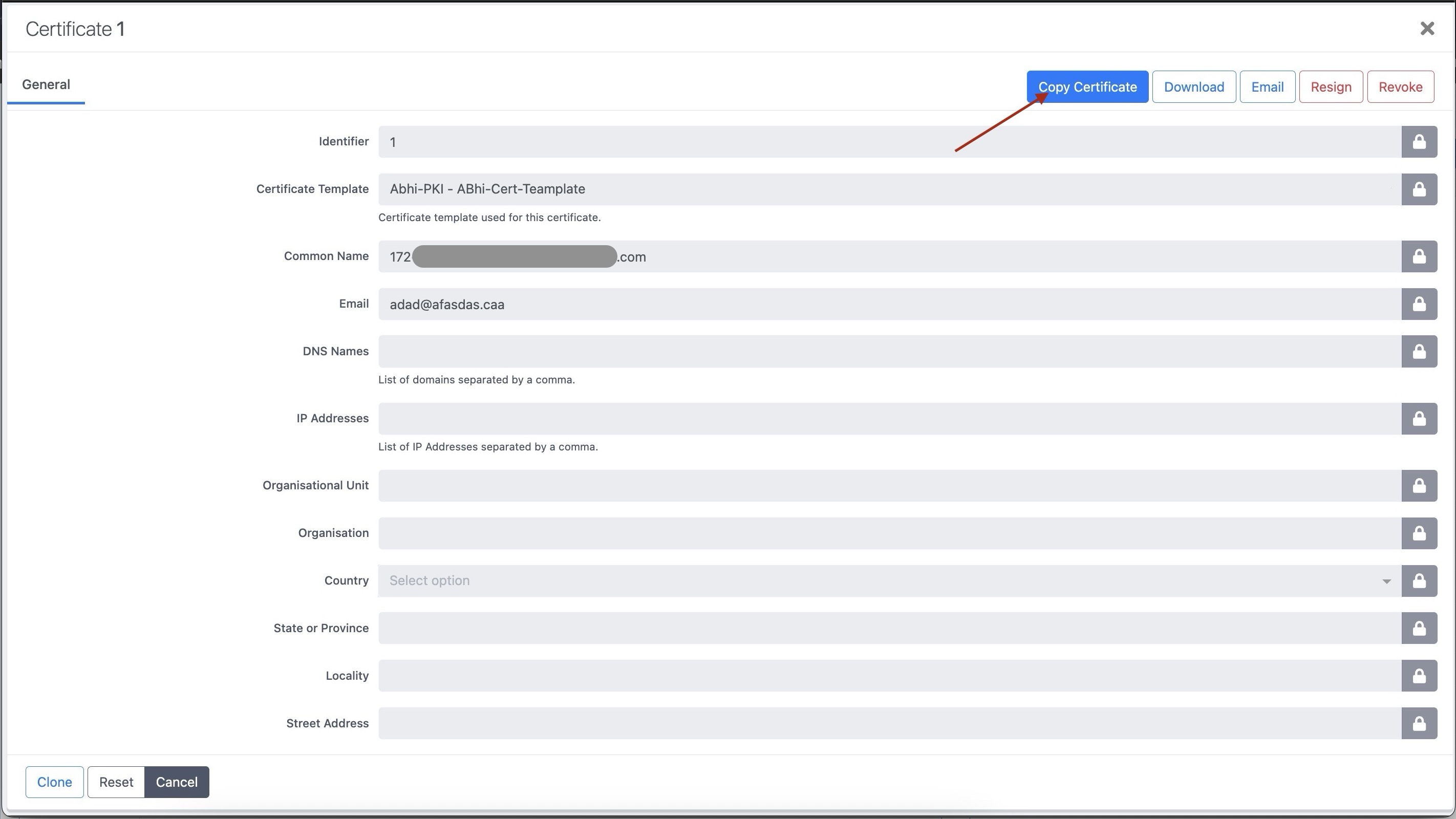
-
To Apply the Certificate:
- Go to Configuration → System Configuration → SSL Certificates, paste the renewed certificate into the HTTP or RADIUS section, and save.
-
Restart the appropriate services for the changes to take effect from the PacketFence UI:
- Restart haproxy-admin and haproxy-portal if it’s the HTTP certificate.
- Restart radiusd-auth if it’s the Radius certificate.
30.7. Useful commands
If a certificate has been created without using PacketFence for the CSR, the key and the certificate can be extracted from the .p12 file (or file with the .p12 extension).
openssl pkcs12 -in certificate_bundle.p12 -clcerts -nokeys -out/usr/local/pf/conf/ssl/server.crt -passin pass:secret
openssl pkcs12 -in certificate_bundle.p12 -nocerts -nodes -out/usr/local/pf/conf/ssl/server.key -passin pass:secret
openssl req -in mycsr.csr -noout -text
30.8. Glossary
- .pem (Privacy Enhanced Mail): PEM is a base64-encoded certificate or key that is commonly used for transporting certificates over the internet or through email. It is a text file that contains a certificate or a private key in plain text.
- .pfx (Personal Information Exchange): PFX is a binary format used for storing a certificate with its associated private key. It is often used in Microsoft Windows systems and can also contain additional intermediate certificates required to establish a chain of trust.
- .crt (Certificate): CRT is a commonly used file extension for a digital certificate. It contains a public key, along with additional information about the certificate, such as the issuer and expiration date.
- .key (Key): KEY is a file extension used to indicate a private key. Private keys are used to decrypt data that has been encrypted using the corresponding public key in a digital certificate.
31. Troubleshooting PacketFence
31.1. RADIUS Audit Log
PacketFence RADIUS auditing module tracks all incoming RADIUS requests/responses. Access via Auditing → RADIUS Audit Log. Advanced search criteria create complex, savable search expressions. Click log entries to view endpoint information, request origin, and RADIUS payload between NAS and PacketFence.
31.2. Log files
Log files are in /usr/local/pf/logs. Each service has its own log
file, except
packetfence.log which contains logs from multiple services. View complete log
file list via Audit → Live logs menu in web admin.
Main logging configuration is in /usr/local/pf/conf/log.conf.
Contains
packetfence.log configuration (Log::Log4Perl) - normally no modification
needed. Service-specific logging configurations are in
/usr/local/pf/conf/log.conf.d/.
Key Log Files for Troubleshooting:
-
packetfence.log: General PacketFence application logs -
radius.log: FreeRADIUS authentication and accounting logs -
mariadb.log: Database server logs (renamed from mariadb_error.log in v12+) -
httpd.apache: Apache web server logs (consolidated from multiple httpd logs in v12+)
Useful Log Monitoring Commands:
# Monitor live PacketFence logstail -f /usr/local/pf/logs/packetfence.log# Watch for database errorstail -f /usr/local/pf/logs/mariadb.log# Monitor RADIUS authenticationtail -f /usr/local/pf/logs/radius.log# Check system messages for hardware issuesdmesg | grep -i error# Real-time system log monitoringjournalctl -f
Log File Name Changes (v12.0+):
- MariaDB: mariadb_error.log → mariadb.log
- Apache logs: Multiple files consolidated to httpd.apache
31.3. RADIUS Debugging
Check FreeRADIUS logs at /usr/local/pf/logs/radius.log.
If needed, run FreeRADIUS in debug mode using these commands:
For the authentication radius process:
radiusd -X -d /usr/local/pf/raddb -n auth
For the accounting radius process:
radiusd -X -d /usr/local/pf/raddb -n acct
Additionally there is a raddebug tool that can extract debug logs from a
running FreeRADIUS daemon. PacketFence’s FreeRADIUS is pre-configured with
such support.
In order to have an output from raddebug, you need to either:
-
Make sure user
pfhas a shell in/etc/passwd, add/usr/sbinto PATH (export PATH=/usr/sbin:$PATH) and executeraddebugaspf -
Run
raddebugas root (less secure!)
Now you can run raddebug easily:
raddebug -t 300 -f /usr/local/pf/var/run/radiusd.sock
The above will output FreeRADIUS' authentication debug logs for 5 minutes.
Use the following to debug radius accounting:
raddebug -t 300 -f /usr/local/pf/var/run/radiusd-acct.sock
See man raddebug for all the options.
31.4. Authentication Failures
If authentication fails for users or devices:
-
Check RADIUS audit log via Auditing → RADIUS Audit Log to trace authentication flow
-
Verify authentication source configuration in Configuration → Policies and Access Control → Authentication Sources
-
For Active Directory issues:
-
Verify domain join status:
realm list -
Check domain controller connectivity:
kinit username@DOMAIN.COM - Test LDAP connectivity from PacketFence server
-
Verify domain join status:
-
For external authentication sources (LDAP, RADIUS), verify network connectivity and credentials
-
Check that user/device exists in authentication source and has proper permissions
-
For certificate-based authentication (802.1X), verify:
- Certificate Authority (CA) configuration
- Certificate validity and expiration
- EAP-TLS profile settings
Advanced Active Directory Troubleshooting:
-
Domain Controller Failover: For multiple AD servers, ensure:
-
Set 'Sticky DC' parameter to
*in domain configuration - Specify multiple DNS servers alternating between availability zones
-
Example:
10.0.1.100,10.0.2.100,10.0.1.101,10.0.2.101
-
Set 'Sticky DC' parameter to
-
Winbindd Failover Issues: Some samba/winbindd versions don’t failover correctly:
- Enable monit to automatically restart winbindd on DC failures
- Monitor authentication failures and restart services when needed
-
Individual Machine Accounts: For cluster deployments, use individual machine accounts for each node to avoid secure connection binding issues
-
Certificate Issues: For ADCS/PKI integration:
- Apply required hotfixes before configuration
- Check for "The RPC Server is unavailable" errors after ADCS service restart
- Verify SSL certificate validity and hostname matching
31.5. Network Connectivity Issues
For network-related problems:
Basic Network Diagnostics:
-
Verify interface configuration and IP addresses:
ip addr show -
Check network service status:
/usr/local/pf/bin/pfcmd service pf status | grep -E "(dhcpd|pfdhcp|keepalived)" -
Test connectivity to network devices (switches, wireless controllers):
ping switch-ip-address -
Verify SNMP connectivity to network devices:
snmpwalk -v2c -c community switch-ip-address system -
For VLAN enforcement issues, check switch configuration and trunk port settings
-
Verify firewall rules allow required traffic between PacketFence and network devices
31.5.1. Advanced Network Issues
-
Large Registration Network Issues: In large environments, check for ARP table overflow symptoms:
- DHCP not assigning IPs properly
- Failed pings in registration/quarantine VLANs
-
Check system logs:
dmesg | grep "Neighbour table overflow"
-
VLAN Segmentation: Ensure VLAN reaches from client to DHCP infrastructure to PacketFence server
-
Keepalived Issues: If virtual IP addresses aren’t working properly:
/usr/local/pf/bin/pfcmd service keepalived restart
31.6. Service Startup Failures
If services fail to start after upgrade or configuration changes:
-
Check service status using:
/usr/local/pf/bin/pfcmd service pf status -
Examine log files in
/usr/local/pf/logsfor specific service error messages -
Verify database connectivity before starting services
-
Check configuration syntax using:
/usr/local/pf/bin/pfcmd checkup -
For network-related service failures, verify interface configuration and IP addresses
-
If httpd services fail, check Apache error logs and verify SSL certificate validity
31.6.1. Common Service Issues
-
Admin Interface Access Issues: If admin interface shows "Internet Explorer cannot display the webpage":
-
Check if admin interface is started:
/usr/local/pf/bin/pfcmd service httpd.admin start - For IE 8-10: Enable TLS v1.2 in browser settings (Tools → Internet Options → Advanced)
- Verify SSL certificate matches hostname
-
Check if admin interface is started:
-
MariaDB Service Issues: If MariaDB fails to start, check:
tail -f /usr/local/pf/logs/mariadb.log -
Service Restart Commands: For specific service troubleshooting:
# Restart RADIUS services/usr/local/pf/bin/pfcmd service radiusd restart# Restart NTLM authentication APIsystemctl restart packetfence-ntlm-auth-api# Restart specific detection services/usr/local/pf/bin/pfcmd service pfdetect restart/usr/local/pf/bin/pfcmd service pfqueue restart -
Monitoring Service Logs: Use journalctl for real-time log monitoring:
journalctl -f -u packetfence-mariadbjournalctl -f # Monitor all system logs
31.7. Database Connectivity Issues
Check PacketFence application can connect to the database by emulating how PacketFence connects:
mysql -u $(perl -I/usr/local/pf/lib_perl/lib/perl5 -I/usr/local/pf/lib -Mpf::db -e 'print $pf::db::DB_Config->{user}') -p$(perl -I/usr/local/pf/lib_perl/lib/perl5 -I/usr/local/pf/lib -Mpf::db -e 'print $pf::db::DB_Config->{pass}') -h $(perl -I/usr/local/pf/lib_perl/lib/perl5 -I/usr/local/pf/lib -Mpf::db -e 'print $pf::db::DB_Config->{host}') pf
mysql -u $(perl -I/usr/local/pf/lib -Mpf::db -e 'print $pf::db::DB_Config->{user}') -p$(perl -I/usr/local/pf/lib -Mpf::db -e 'print $pf::db::DB_Config->{pass}') -h $(perl -I/usr/local/pf/lib -Mpf::db -e 'print $pf::db::DB_Config->{host}') pf
If you got a prompt, it means PacketFence must be able to connect to the database.
To perform a small query to the database using PacketFence codebase:
/usr/local/pf/bin/pfcmd checkup
If the command doesn’t return any database error, PacketFence is able to perform reads on database.
Common Database Connection Issues:
-
Too Many Connections: Default MariaDB limit is often too low (100). Increase to at least 300 for wireless environments with heavy RADIUS traffic.
-
Host Blocked: After 10 connection timeouts, MariaDB may block the host. Check for "Host <hostname> is blocked" errors.
-
Custom Database Configuration: If API requests return errors, check
packetfence.logfor full MySQL error messages. -
Configuration Reload: After database configuration changes, run:
/usr/local/pf/bin/pfcmd configreload hard
31.8. Performance and Optimization Issues
Large Environment Considerations:
-
ARP Table Overflow: In large registration networks, symptoms include:
- DHCP not assigning IPs properly
- Failed pings in registration/quarantine VLANs
-
System log message: "Neighbour table overflow"
**Solution**: Increase kernel ARP cache settings in `/etc/sysctl.conf`:net.ipv4.neigh.default.gc_thresh1 = 2048net.ipv4.neigh.default.gc_thresh2 = 4096net.ipv4.neigh.default.gc_thresh3 = 8192sysctl -p
-
Database Connection Limits: For wireless environments with heavy RADIUS traffic:
- Increase MariaDB max_connections from default 100 to at least 300
- Monitor for "Too many connections" errors
- Check for "Host <hostname> is blocked" messages after connection timeouts
-
Memory and Resource Usage: Monitor system resources during peak usage:
# Check memory usagefree -m# Monitor active processestop -p $(pgrep -d',' -f packetfence)# Check disk spacedf -h /usr/local/pf/logs /var/lib/mysql
Guest Pre-registration Security:
- Pre-registration exposes PacketFence functionality on the Internet
- Apply critical OS updates and PacketFence security fixes
- Ensure valid MTA configuration for email relay
- Monitor /signup page access logs for suspicious activity
31.9. Captive Portal Issues
Portal Not Appearing:
-
Network Configuration: Verify portal interface configuration:
- Check that 'portal' interface type is configured
- Verify IP addresses and VLAN configuration
- Test network connectivity from client to PacketFence portal IP
-
Apache/HTTP Services: Check portal web services:
/usr/local/pf/bin/pfcmd service pf status | grep httpdsystemctl status httpd.portal -
DNS and Redirection: Verify DNS redirection is working:
- Check that unregistered devices receive portal IP in DNS responses
- Verify iptables rules for portal redirection
-
Test with:
nslookup google.comfrom unregistered client
31.9.1. Content Security Policy (CSP) Issues
-
CSP Blocking Content: If portal content is blocked by CSP:
- Disable CSP headers via Configuration → System Configuration → Main Configuration → Advanced → CSP headers for Captive Portal
- Check browser developer tools for CSP violation errors
- Verify all external content sources are whitelisted
31.9.2. SSL/TLS Certificate Issues
-
Certificate Problems: For HTTPS portal access:
- Verify SSL certificate matches portal hostname
- Check certificate expiration date
- For self-signed certificates, ensure proper trust chain
31.9.3. Pre-registration Security
-
External Access Issues: When pre-registration is enabled:
- Verify perimeter firewall allows access to port 443
- Check that domain name resolves to management interface IP
-
Monitor for security attacks on exposed
/signupendpoint
32. Commercial Support and Contact Information
For any questions or comments, do not hesitate to contact us by writing an email to: support@inverse.ca.
Akamai - Inverse team (https://www.packetfence.com) offers professional services around PacketFence to help organizations deploy the solution, customize, migrate versions or from another system, performance tuning or aligning with best practices.
Hourly rates or support packages are offered to best suit your needs.
Please visit https://www.packetfence.com for details.
33. GNU Free Documentation License
Please refer to https://www.gnu.org/licenses/fdl-1.2.txt for the full license.
34. Appendix
Appendix A: Administration Tools
34.A.1. pfcmd
pfcmd is the command line interface to most PacketFence functionalities.
When executed without any arguments pfcmd returns a basic help message with
all main options:
Usage:pfcmd <command> [options]Commandscache | manage the cache subsystemcheckrequirements | check system hardware requirements (RAM, CPU, disk)checkup | perform a sanity checkup and report any problemsclass | view security event classesconfigreload | reload the configutionconnectionprofileconfig | query/modify connection profile configuration parametersfingerbank | Fingerbank related commandsfixpermissions | fix permissions on pf treefloatingnetworkdeviceconfig | query/modify floating network devices configuration parametersgeneratemariadbconfig | generate the MariaDB configurationgeneratemonitconfig | generate the monit configurationgeneratesyslogconfig | generate the syslog configurationhelp | show help for pfcmd commandsimport | bulk import of information into the databaseipmachistory | IP/MAC historylocationhistorymac | Switch/Port historylocationhistoryswitch | Switch/Port historynetworkconfig | query/modify network configuration parametersnode | manipulate node entriespfconfig | interact with pfconfigpfcron | run pfcron taskspfqueue | query/modify pfqueue tasks and countersreload | rebuild fingerprint or security events tables without restartreloadiptablesrules | rebuild iptables rules without restartreloadip6tablesrules | rebuild ip6tables rules without restartservice | start/stop/restart and get PF daemon statusswitchconfig | query/modify switches.conf configuration parametersversion | output version informationsecurity_event | manipulate security eventssecurity_eventconfig | query/modify security_events.conf configuration parametersPlease view "pfcmd help <command>" for details on each option
The node view option shows all information contained in the node database table for a specified MAC address
# /usr/local/pf/bin/pfcmd node view 52:54:00:12:35:02mac|pid|detect_date|regdate|unregdate|status|user_agent|computername|notes|last_arp|last_dhcp|switch|port|vlan|dhcp_fingerprint52:54:00:12:35:02|1|2008-10-23 17:32:16||||unreg||||2008-10-23 21:12:21|||||
Appendix B: Restoring a Percona XtraBackup or Mariabackup dump
When Percona XtraBackup or Mariabackup is enabled for nightly backup,
use the following instructions to restore it. In this example
/root/backup/packetfence-db-dump-innobackup-2016-12-20_00h31.xbstream.gz
will be restored
First, create a restore directory, move the backup to it and gunzip the backup:
# mkdir /root/backup/restore# cd /root/backup/restore# cp ../packetfence-db-dump-innobackup-2016-12-20_00h31.xbstream.gz .# gunzip packetfence-db-dump-innobackup-2016-12-20_00h31.xbstream.gz
Then extract the xbstream data (for XtraBackup):
# xbstream -x < packetfence-db-dump-innobackup-2016-12-20_00h31.xbstream
Then extract the xbstream data (for Mariabackup):
# mbstream -x < packetfence-db-dump-innobackup-2016-12-20_00h31.xbstream
Once done, many files should be extracted in the restore dir. Now, place the xbstream back in the backup directory
# mv packetfence-db-dump-innobackup-2016-12-20_00h31.xbstream ../
Next, apply the innodb log (for XtraBackup):
# innobackupex --apply-log ./
Next, apply the innodb log (for Mariabackup):
# mariabackup --prepare --target-dir=./
We will now stop MariaDB, move the existing data directory and replace it by the data that was extracted:
For XtraBackup:
# service packetfence-mariadb stop# mv /var/lib/mysql /var/lib/mysql.bak# mkdir /var/lib/mysql# mv * /var/lib/mysql# chown -R mysql: /var/lib/mysql# service packetfence-mariadb start
For Mariabackup:
# service packetfence-mariadb stop# mv /var/lib/mysql /var/lib/mysql.bak# mkdir /var/lib/mysql# mariabackup --innobackupex --defaults-file=/usr/local/pf/var/conf/mariadb.conf --move-back --force-non-empty-directories ./# chown -R mysql: /var/lib/mysql# service packetfence-mariadb start
Should the service fail to start, check the MariaDB logs.
Appendix C: How to restore a standalone PacketFence server ?
Starting from PacketFence 11.0, use the export/import mechanism.
Appendix D: How to deploy PacketFence on Linode ?
34.D.1. Introduction
This section will guide you into the high-level steps required to deploy PacketFence on Linode. Linode is an Infrastructure as a Service (IaaS) that provides cloud computing services which can be leveraged by PacketFence. This is often the preferred deployment option for Cloud-first organizations.
34.D.2. Installation and Configuration Steps
First, you need to create three 'Debian 12' or 'Rocky 8' Linodes in the same region. The 'Dedicated 16GB' plan or above is required and make sure Private IP is enabled for each instance.
Once done, make sure to configure the firewall policy similar to the following screenshot:
Then, perform a standard PacketFence installation on each Linode. Once completed, from Linode’s cloud management interface, configure a NodeBalancer for ports 80, 443, 1443, 9090 and 9999 as shown in the following screenshot:
Once completed, Go through the PacketFence Clustering Installation Guide.
For the IP addresses in the CLUSTER sections, use the public IP of the
NodeBalancer above. For the IP addresses of the servers themselves, use their
private IP addresses. No registration/isolation VLANs are supported at the
moment. If you want to perform enforcement with PacketFence, you will have to
use Web Authentication. Once done building the cluster, disable 'Proxy RADIUS
using virtual IP' and 'Use virtual IP for access reevaluation' from the
Configuration → System Configuration → Cluster configuration section and
restart the radiusd-load_balancer service. Once completed, the file
/usr/local/pf/conf/cluster.conf should be similar to:
[CLUSTER]management_ip=172.105.12.210[CLUSTER interface eth0]ip=172.105.12.210[cluster-1]management_ip=192.168.139.40[cluster-1 interface eth0]ip=192.168.139.40[cluster-2]management_ip=192.168.129.9[cluster-2 interface eth0]ip=192.168.129.9[cluster-3]management_ip=192.168.139.254[cluster-3 interface eth0]ip=192.168.139.254
Then, make sure you mask keepalived so it does not mount a VIP on your server:
systemctl mask packetfence-keepalived
Finally, you must configure a secure way to reach your Cloud-hosted version of PacketFence so that your NAS devices can talk to it in a secure way. One approach is to use a site-to-site VPN. Another approach is to use the PacketFence Connector.